Installation
INSTALLATION
PROCEDURE
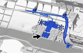
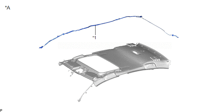
1. INSTALL NO. 2 ANTENNA CORD SUB-ASSEMBLY (w/ Manual (SOS) Switch)
(a) Engage the 4 clamps to install the No. 2 antenna cord sub-assembly.
(b) Connect the connector.
2. INSTALL NO. 3 ANTENNA CORD SUB-ASSEMBLY
HINT:
Butyl
tape and adhesive tape are not available as supply parts. If these
pieces of tape still have enough adhesion to secure the No. 3 antenna
cord sub-assembly to the roof headlining assembly, reuse them. If the
adhesive tape and/or the butyl tape is no longer sticky, apply new tape
following the procedure below.
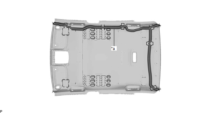
(a) Apply new butyl tape.
for Normal Roof:
|
*a | Marking |
- | - |
 |
Butyl Tape | - |
- |
for Moon Roof:
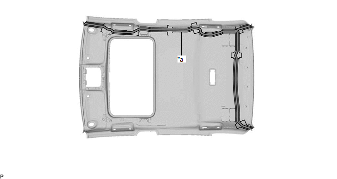
|
*a | Marking |
- | - |
 |
Butyl Tape | - |
- |
(1) Remove the old butyl tape from the roof headlining assembly.
(2) Prepare an appropriate amount of new butyl tape.
HINT:
Be careful not to touch the adhesive surface.
(3)
Apply the butyl tape to the roof headlining assembly while aligning the
tape with the markings on the roof headlining assembly.
(4) Peel off the release paper from the butyl tape.
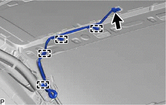
(b)
Align the marking tape (A) on the No. 3 antenna cord sub-assembly with
the protrusion on the front of the roof headlining assembly and wrap
tape around the No. 3 antenna cord sub-assembly and protrusion of the
roof headlining assembly.
for Normal Roof:
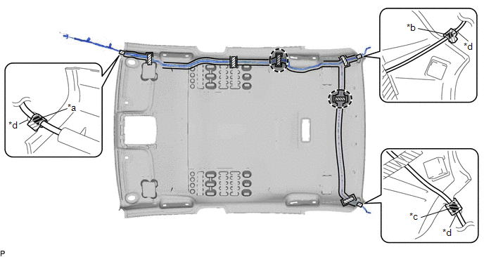
|
*a | Marking Tape (A) |
*b | Marking Tape (B) |
|
*c | Marking Tape (C) |
*d | Protrusion |
 |
Adhesive Tape |
 |
Adjustment Area |
for Moon Roof:
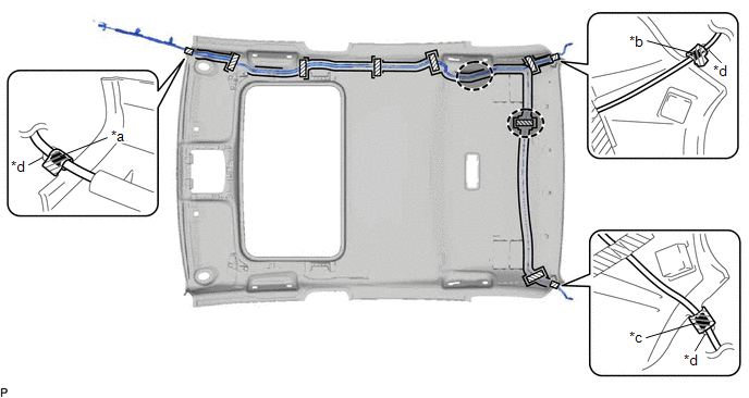
|
*a | Marking Tape (A) |
*b | Marking Tape (B) |
|
*c | Marking Tape (C) |
*d | Protrusion |
 |
Adhesive Tape |
 |
Adjustment Area |
(c)
Align the marking tape (B) on the No. 3 antenna cord sub-assembly with
the protrusion on the rear of the roof headlining assembly and wrap tape
around the No. 3 antenna cord sub-assembly and protrusion of the roof
headlining assembly.
(d) Align the marking tape (C) on
the No. 3 antenna cord sub-assembly with the protrusion on the rear of
the roof headlining assembly and wrap tape around the No. 3 antenna cord
sub-assembly and protrusion of the roof headlining assembly.
(e) Install the No. 3 antenna cord sub-assembly to the roof headlining assembly.
NOTICE:
- Make sure that there are no gaps between the roof headlining assembly
and No. 3 antenna cord sub-assembly, and that the No. 3 antenna cord
sub-assembly is not twisted.
- Make sure the No. 3 antenna cord assembly is securely installed. If any
part of the No. 3 antenna cord sub-assembly is loose, it will cause an
abnormal noise.
HINT:
Secure the extra length of the No. 3 antenna cord sub-assembly in the adjustment area.
(f) Apply the adhesive tape as shown in the illustration to secure the No. 3 antenna cord sub-assembly.
3. INSTALL ROOF HEADLINING ASSEMBLY
Click here

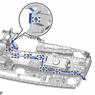
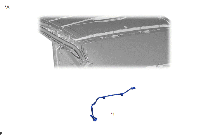
4. INSTALL NO. 4 ANTENNA CORD SUB-ASSEMBLY
(a) Engage the 8 clamps to install the No. 4 antenna cord sub-assembly.
(b) Engage the 2 claws.
(c) Connect the connector.
5. INSTALL NO. 3 HEATER TO REGISTER DUCT SUB-ASSEMBLY
Click here 
6. INSTALL DEFROSTER NOZZLE ASSEMBLY
Click here 
7. INSTALL NO. 2 SIDE DEFROSTER NOZZLE DUCT
Click here 
8. INSTALL NO. 1 SIDE DEFROSTER NOZZLE DUCT
Click here 
9. INSTALL INSTRUMENT PANEL SAFETY PAD SUB-ASSEMBLY
Click here 
Removal
REMOVAL
CAUTION / NOTICE / HINT
The
necessary procedures (adjustment, calibration, initialization, or
registration) that must be performed after parts are removed and
installed, or replaced during antenna cord sub-assembly
removal/installation are shown below.
Necessary Procedure After Parts Removed/Installed/Replaced (for Gasoline Model) |
Replaced Part or Performed Procedure |
Necessary Procedure | Effect/Inoperative Function When Necessary Procedures are not Performed |
Link |
|
*: When performing learning using the Techstream.
Click here  |
|
Disconnect cable from negative battery terminal |
Perform steering sensor zero point calibration |
Lane Departure Alert System (w/ Steering Control) |
 |
|
Pre-collision System |
|
Intelligent Clearance Sonar System* |
|
Lighting System (for Gasoline Model with Cornering Light) |
|
Memorize steering angle neutral point |
Parking Assist Monitor System |
 |
|
Panoramic View Monitor System |
 |
|
Front passenger seat | Zero point calibration (Occupant classification system) |
- Occupant classification system
- Passenger airbag ON/OFF indicator
- Airbag system (Front passenger side)
- Seat belt warning system (Front passenger)
|
 |
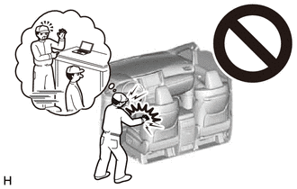
CAUTION:
Some
of these service operations affect the SRS airbag system. Read the
precautionary notices concerning the SRS airbag system before servicing.
Click here

 Necessary Procedure After Parts Removed/Installed/Replaced (for HV Model)
 |
Replaced Part or Performed Procedure |
Necessary Procedure | Effect/Inoperative Function When Necessary Procedures are not Performed |
Link |
|
*: When performing learning using the Techstream.
Click here  |
|
Disconnect cable from negative auxiliary battery terminal |
Perform steering sensor zero point calibration |
Lane Departure Alert System (w/ Steering Control) |
 |
|
Pre-collision System |
|
Intelligent Clearance Sonar System* |
|
Lighting System (for HV Model with Cornering Light) |
|
Memorize steering angle neutral point |
Parking Assist Monitor System |
 |
|
Panoramic View Monitor System |
 |
|
Front passenger seat | Zero point calibration (Occupant classification system) |
- Occupant classification system
- Passenger airbag ON/OFF indicator
- Airbag system (Front passenger side)
- Seat belt warning system (Front passenger)
|
 |
CAUTION:
Some
of these service operations affect the SRS airbag system. Read the
precautionary notices concerning the SRS airbag system before servicing.
Click here


PROCEDURE
1. REMOVE INSTRUMENT PANEL SAFETY PAD SUB-ASSEMBLY
Click here

2. REMOVE NO. 1 SIDE DEFROSTER NOZZLE DUCT
Click here 
3. REMOVE NO. 2 SIDE DEFROSTER NOZZLE DUCT
Click here 
4. REMOVE DEFROSTER NOZZLE ASSEMBLY
Click here 
5. REMOVE NO. 3 HEATER TO REGISTER DUCT SUB-ASSEMBLY
Click here 
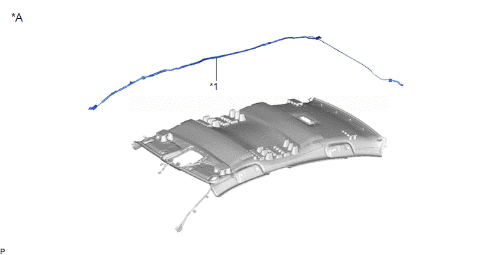
6. REMOVE NO. 4 ANTENNA CORD SUB-ASSEMBLY
| (a) Disconnect the connector. | |
(b) Disengage the 2 claws.
| (c) Disengage the 8 clamps and remove the No. 4 antenna cord sub-assembly. |
|
7. REMOVE ROOF HEADLINING ASSEMBLY
Click here

8. REMOVE NO. 3 ANTENNA CORD SUB-ASSEMBLY
(a) Remove the adhesive tape from the roof headlining assembly.
for Normal Roof:
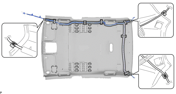
 | Adhesive Tape |
- | - |
for Moon Roof:
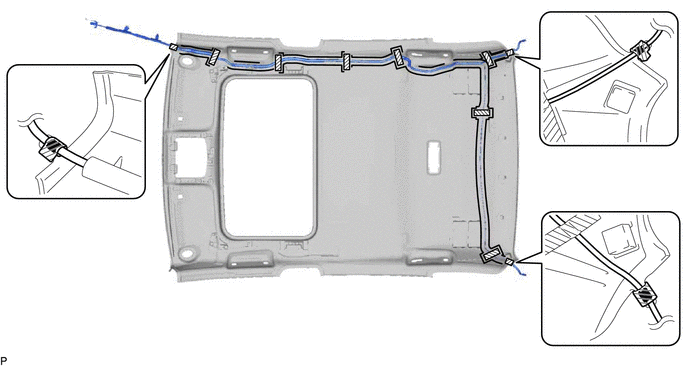
 | Adhesive Tape |
- | - |
(b) Remove the No. 3 antenna cord sub-assembly from the roof headlining assembly.
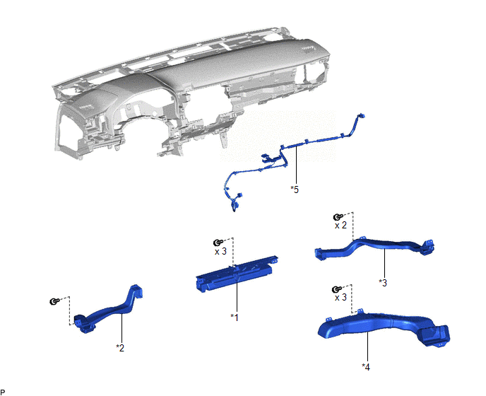
9. REMOVE NO. 2 ANTENNA CORD SUB-ASSEMBLY (w/ Manual (SOS) Switch)
| (a) Disconnect the connector. | |
(b) Disengage the 4 clamps to remove the No. 2 antenna cord sub-assembly.


 Necessary Procedure After Parts Removed/Installed/Replaced (for HV Model)


