Components
COMPONENTS
ILLUSTRATION
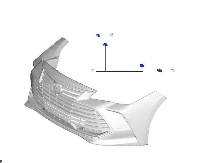
|
*1 | FRONT CENTER ULTRASONIC SENSOR |
*2 | FRONT CORNER ULTRASONIC SENSOR |
Inspection
INSPECTION
PROCEDURE
1. INSPECT FRONT CENTER ULTRASONIC SENSOR
| (a) Measure the resistance according to the value(s) in the table below.
Standard Resistance: |
Tester Connection | Condition |
Specified Condition | |
4 (BI) - 6 (EI) | Always |
10 kΩ or higher | |
4 (BI) - 1 (BO) | Always |
Below 1 Ω | |
5 (SI) - 2 (SO) | Always |
Below 30 Ω | |
6 (EI) - 3 (EO) | Always |
Below 1 Ω | If the result is not as specified, replace the front center ultrasonic sensor. |
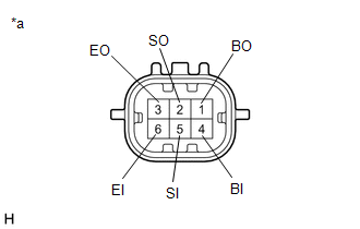 |
|
*a | Component without harness connected
(Front Center Ultrasonic Sensor) | | |
2. INSPECT FRONT CORNER ULTRASONIC SENSOR
(a) for RH Side:
| (1) Measure the resistance according to the value(s) in the table below.
Standard Resistance: |
Tester Connection | Condition |
Specified Condition | |
4 (BI) - 6 (EI) | Always |
10 kΩ or higher | |
4 (BI) - 1 (BO) | Always |
Below 1 Ω | |
5 (SI) - 2 (SO) | Always |
Below 30 Ω | |
6 (EI) - 3 (EO) | Always |
Below 1 Ω | If the result is not as specified, replace the front corner ultrasonic sensor RH. |
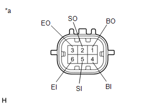 |
|
*a | Component without harness connected
(Front Corner Ultrasonic Sensor RH) | | |
(b) for LH Side:
| (1) Measure the resistance according to the value(s) in the table below.
Standard Resistance: |
Tester Connection | Condition |
Specified Condition | |
4 (BI) - 6 (EI) | Always |
10 kΩ or higher | |
4 (BI) - 1 | Always |
Below 1 Ω | |
5 (SI) - 2 | Always |
Below 30 Ω | |
6 (EI) - 3 | Always |
Below 1 Ω | If the result is not as specified, replace the front corner ultrasonic sensor LH. |
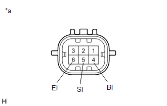 |
|
*a | Component without harness connected
(Front Corner Ultrasonic Sensor LH) | | |
Installation
INSTALLATION
PROCEDURE
1. INSTALL FRONT CORNER ULTRASONIC SENSOR
HINT:
- Use the same procedure for the RH side and LH side.
- The following procedure is for the LH side.
(a) Engage the 2 claws to install the front corner ultrasonic sensor as shown in the illustration.
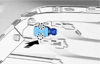
 |
Install in this Direction |
(b) Connect the connector.
2. INSTALL FRONT CENTER ULTRASONIC SENSOR
HINT:
- Use the same procedure for the RH side and LH side.
- The following procedure is for the LH side.
(a) Engage the 2 claws to install the front center ultrasonic sensor as shown in the illustration.
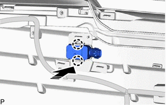
 |
Install in this Direction |
(b) Connect the connector.
3. INSTALL FRONT BUMPER ASSEMBLY
Click here

4. PERFORM CALIBRATION
for Gasoline Model: Click here

for HV Model: Click here

SST: 09989-00020
Removal
REMOVAL
CAUTION / NOTICE / HINT
The
necessary procedures (adjustment, calibration, initialization, or
registration) that must be performed after parts are removed and
installed, or replaced during ultrasonic sensor removal/installation are
shown below.
Necessary Procedure After Parts Removed/Installed/Replaced (for Gasoline Model) |
Replaced Part or Performed Procedure |
Necessary Procedure | Effect/Inoperative Function When Necessary Procedures are not Performed |
Link |
- Front bumper assembly
- Ultrasonic sensor
|
- Measure ultrasonic sensor detection angle
- Ultrasonic sensor detection angle registration
|
- Intelligent Clearance Sonar System
- Intuitive Parking Assist System
|
 |
|
Front bumper assembly (w/ Panoramic View Monitor System) |
Front television camera view adjustment |
Panoramic View Monitor System |
 |
Necessary Procedure After Parts Removed/Installed/Replaced (for HV Model) |
Replaced Part or Performed Procedure |
Necessary Procedure | Effect/Inoperative Function When Necessary Procedures are not Performed |
Link |
- Front bumper assembly
- Ultrasonic sensor
|
- Measure ultrasonic sensor detection angle
- Ultrasonic sensor detection angle registration
|
- Intelligent Clearance Sonar System
- Intuitive Parking Assist System
|
 |
|
Front bumper assembly (w/ Panoramic View Monitor System) |
Front television camera view adjustment |
Panoramic View Monitor System |
 |
PROCEDURE
1. REMOVE FRONT BUMPER ASSEMBLY
Click here

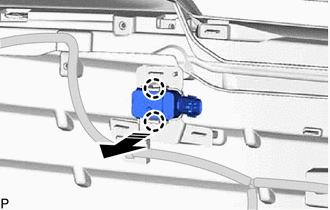
2. REMOVE FRONT CENTER ULTRASONIC SENSOR
HINT:
- Use the same procedure for the RH side and LH side.
- The following procedure is for the LH side.
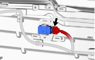
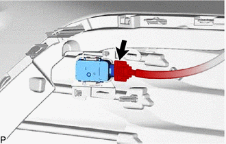
| (a) Disconnect the connector. |
|
(b) Disengage the 2 claws and remove the front center ultrasonic sensor as shown in the illustration.
 |
Remove in this Direction |
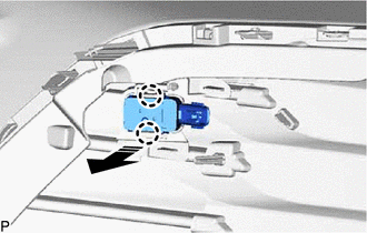
3. REMOVE FRONT CORNER ULTRASONIC SENSOR
HINT:
- Use the same procedure for the RH side and LH side.
- The following procedure is for the LH side.
| (a) Disconnect the connector. |
|
(b) Disengage the 2 claws and remove the front corner ultrasonic sensor as shown in the illustration.
 |
Remove in this Direction |


