Components
COMPONENTS
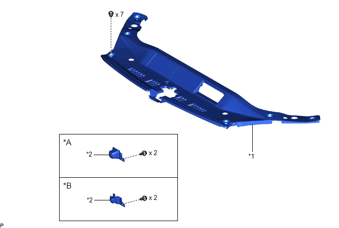
ILLUSTRATION
|
*A | for Bar Type Radiator Grille |
*B | for Mesh Type Radiator Grille |
|
*1 | COOL AIR INTAKE DUCT SEAL |
*2 | FRONT TELEVISION CAMERA ASSEMBLY |
Installation
INSTALLATION
PROCEDURE
1. INSTALL FRONT TELEVISION CAMERA ASSEMBLY
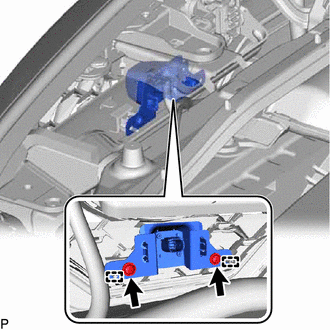
(a) Engage the 2 guides.
(b) Install the front television camera assembly with the 2 screws.
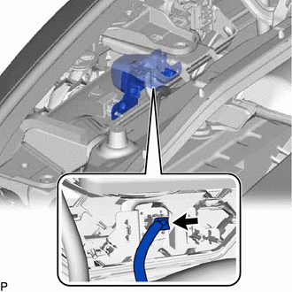
(c) Connect the connector.
2. INSTALL COOL AIR INTAKE DUCT SEAL
Click here

3. PERFORM CALIBRATION
for Gasoline Model: Click here
for HV Model: Click here
Removal
REMOVAL
CAUTION / NOTICE / HINT
The necessary procedures (adjustment, calibration, initialization, or registration) that must be performed after parts are removed and installed, or replaced during front television camera assembly removal/installation are shown below.
Necessary Procedure After Parts Removed/Installed/Replaced (for Gasoline Model)|
Replaced Part or Performed Procedure |
Necessary Procedure | Effect/Inoperative Function When Necessary Procedures are not Performed |
Link |
|---|---|---|---|
| Front television camera assembly |
Front television camera view adjustment |
Panoramic View Monitor System |
|
|
Replaced Part or Performed Procedure |
Necessary Procedure | Effect/Inoperative Function When Necessary Procedures are not Performed |
Link |
|---|---|---|---|
| Front television camera assembly |
Front television camera view adjustment |
Panoramic View Monitor System |
|
PROCEDURE
1. REMOVE COOL AIR INTAKE DUCT SEAL
Click here

2. REMOVE FRONT TELEVISION CAMERA ASSEMBLY
| (a) Disconnect the connector. |
|
| (b) Remove the 2 screws. |
|
(c) Disengage the 2 guides to remove the front television camera assembly.
Toyota Avalon (XX50) 2019-2022 Service & Repair Manual > Hybrid Control System: Hybrid/EV Battery Precharge Contactor Actuator Stuck Closed (P0AE173)
DTC SUMMARY MALFUNCTION DESCRIPTION The hybrid vehicle control ECU detects a stuck closed malfunction of a precharge relay stuck malfunction on the HV battery negative side. The cause of this malfunction may be one of the following: Inverter voltage sensor (VH) internal circuit malfunction Voltage s ...