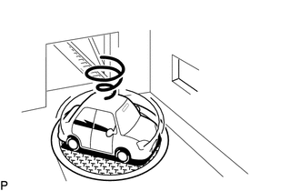
PROCEDURE 1. CHECK CONDITION (a) Check with the customer if the vehicle has been turned by a turntable. OK: Vehicle has not been turned by a turntable. HINT: If
the vehicle is turned on a turntable with the engine switch on (IG),
the system may store the angular velocity. As a result, the vehicle
position cursor may deviate. In this case, the vehicle position cursor
will return to normal by turning the engine switch off and back to on
(IG) again with the vehicle completely stopped. PROCEED TO NEXT SUSPECTED AREA SHOWN IN PROBLEM SYMPTOMS TABLE TURN ENGINE SWITCH ON (IG) WHEN VEHICLE IS COMPLETELY STOPPED DATA LIST / ACTIVE TEST DATA LIST NOTICE: In
the table below, the values listed under "Normal Condition" are
reference values. Do not depend solely on these reference values when
deciding whether a part is faulty or not. HINT: Using
the Techstream to read the Data List allows the values or states of
switches, sensors, actuators and other items to be read without removing
any parts. This non-intrusive inspection can be very useful because
intermittent conditions or signals may be discovered before parts or
wiring is disturbed. Reading the Data List information early in
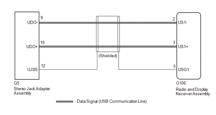
troubleshooting is one way to save diagnostic time. (a) Connect the Techstream to the DLC3. (b) Turn the engine switch on (IG). (c) Turn the Techstream on. (d) Enter the following menus: Body Electrical / Navigation System / Data List. (e) Read the Data List according to the display on the Techstream. Tester Display Measurement Item Range Normal Condition Diagnostic Note Battery Voltage Battery voltage Min.: 0 V, Max.: 24 V 11 to 14 V - Active Dimmer Active dimmer function ON or OFF ON: Active dimmer function on OFF: Active dimmer function off - Tail Light SW Taillight switch ON or OFF ON: Light control switch in tail or head position OFF: Light control switch off or AUTO - Reverse Signal Reverse signal ON or OFF ON: Shift lever in R OFF: Shift lever not in R - Parking Brake Parking brake switch ON or OFF ON: Parking brake applied OFF: Parking brake released - Ignition Engine switch ON or OFF ON: Engine switch on (IG) OFF: Engine switch off or on (ACC) "OFF" is displayed even though the engine switch is on (ACC) Vehicle Speed Maximum wheel speed sensor reading Min.: 0 km/h (0 mph), Max.: 255 km/h (158 mph) Vehicle stopped: 0 km/h (0 mph) When driving at constant speed: No large fluctuations HDMI Line(Blu-ray Disc Player) - Disconnected or Connected Disconnected Not available DESCRIPTION The stereo jack
adapter assembly sends the sound data signal or image data signal from a
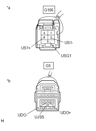
USB device to the radio and display receiver assembly via this circuit. WIRING DIAGRAM PROCEDURE 1. CHECK HARNESS AND CONNECTOR (RADIO AND DISPLAY RECEIVER ASSEMBLY - STEREO JACK ADAPTER ASSEMBLY) (a) Disconnect the G106 radio and display receiver assembly connector. (b) Disconnect the G5 stereo jack adapter assembly connector. (c) Measure the resistance according to the value(s) in the table below. Standard Resistance: Tester Connection Condition Specified Condition G106-2 (US1-) - G5-9 (UDO-) Always Below 1 Ω G106-3 (US1+) - G5-10 (UDO+) Always Below 1 Ω G106-5 (USG1) - G5-12 (UJSS) Always Below 1 Ω G106-2 (US1-) or G5-9 (UDO-) - Body ground Always 10 kΩ or higher G106-3 (US1+) or G5-10 (UDO+) - Body ground Always 10 kΩ or higher G106-5 (USG1) or G5-12 (UJSS) - Body ground Always 10 kΩ or higher *a Front view of wire harness connector (to Radio and Display Receiver Assembly) *b Front view of wire harness connector (to Stereo Jack Adapter Assembly) PROCEED TO NEXT SUSPECTED AREA SHOWN IN PROBLEM SYMPTOMS TABLE REPAIR OR REPLACE HARNESS OR CONNECTORCursor or Map Rotates when Vehicle Stopped
OK

NG
Data List / Active Test
Data Signal Circuit between Radio Receiver and Stereo Jack Adapter
OK

NG
Toyota Avalon (XX50) 2019-2022 Service & Repair Manual > Motor Generator Control System: Drive Motor "A" Circuit Current Out of Range (P0BFF1D)
DTC SUMMARY MALFUNCTION DESCRIPTION This DTC is stored when the motor generator control system is malfunctioning and current does not flow as commanded. The cause of this malfunction may be one of the following: Area Main Malfunction Description Inside of inverter Inverter with converter assembly in ...


