TERMINALS OF ECU
HINT:
Check from the rear of the connector while it is connected to the components.
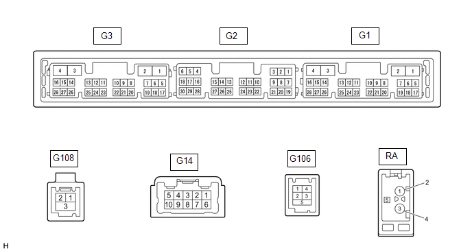
RADIO AND DISPLAY RECEIVER ASSEMBLY
|
Terminal No. (Symbol) | Wiring Color |
Terminal Description | Condition |
Specified Condition |
|---|---|---|---|---|
|
G14-1 (FR+) - G3-1 (GND1) |
LA-LG - BR*1 W - BR*2 |
Sound signal (Front right)*1 Sound signal (Right)*2 |
Audio system playing |
A waveform synchronized with sound signals is output |
|
G14-2 (FL+) - G3-1 (GND1) |
LA-B - BR*1 B - BR*2 |
Sound signal (Front left)*1 Sound signal (Left)*2 |
Audio system playing |
A waveform synchronized with sound signals is output |
|
G14-3 (RL+) - G3-1 (GND1) |
LA-G - BR*1 Y - BR*2 |
Sound signal (Rear left)*1 Voice signal*2 |
Audio system playing*1 Voice guidance sounding*2 |
A waveform synchronized with sound signals is output*1 A waveform synchronized with voice signals is output*2 |
|
G14-4 (RR+) - G3-1 (GND1)*1 |
LA-R - BR | Sound signal (Rear right) |
Audio system playing |
A waveform synchronized with sound signals is output |
|
G14-6 (FR-) - G3-1 (GND1) |
LA-L - BR*1 R - BR*2 |
Sound signal (Front right)*1 Sound signal (Right)*2 |
Audio system playing |
A waveform synchronized with sound signals is output |
|
G14-7 (FL-) - G3-1 (GND1) |
LA-R - BR*1 G - BR*2 |
Sound signal (Front left)*1 Sound signal (Left)*2 |
Audio system playing |
A waveform synchronized with sound signals is output |
|
G14-8 (RL-) - G3-1 (GND1) |
LA-GR - BR*1 BR - BR*2 |
Sound signal (Rear left)*1 Voice signal*2 |
Audio system playing |
A waveform synchronized with sound signals is output |
|
G14-9 (RR-) - G3-1 (GND1)*1 |
LA-G - BR | Sound signal (Rear right) |
Audio system playing |
A waveform synchronized with sound signals is output |
|
G3-1 (GND1) - Body ground |
BR - Body ground | Ground |
Always | Below 1 V |
|
G3-4 (+B1) - G3-1 (GND1) |
R - BR | Power source (+B) |
Power switch off | 11 to 14 V |
|
G3-5 (TX1+)*2 | B |
AVC-LAN communication signal |
- | - |
|
G3-6 (TX1-)*2 | W |
AVC-LAN communication signal |
- | - |
|
G3-10 (AGND) - Body ground |
Shield - Body ground |
Shield ground | Always |
Below 1 V |
|
G3-11 (VAL+) - G3-13 (VA-) |
B - R | Sound signal (Left) |
External device playing (When stereo jack used) |
A waveform synchronized with sound signals is output |
|
G3-12 (VAR+) - G3-13 (VA-) |
W - R | Sound signal (Right) |
External device playing (When stereo jack used) |
A waveform synchronized with sound signals is output |
|
G3-13 (VA-) - G3-1 (GND1) |
R - BR | Ground |
Always | Below 1 V |
|
G3-14 (ADPG) - G3-1 (GND1) |
L - BR | External device connection detection signal |
External device connected |
Below 1 V |
|
External device not connected |
2.1 to 3 V | |||
|
G3-15 (ACC1) - G3-1 (GND1) |
GR - BR | Power source (ACC) |
Power switch off | Below 1 V |
|
Power switch on (ACC) |
11 to 14 V | |||
|
G3-21 (SW1) - G3-24 (SWG) |
W - L | Steering pad switch signal |
No switch pushed | 2.97 to 3.56 V |
|
Seek+ switch pushed | 0.27 to 0.35 V | |||
|
Seek- switch pushed | 0.86 to 1.03 V | |||
|
Volume+ switch pushed |
1.51 to 1.79 V | |||
|
Volume- switch pushed |
2.22 to 2.66 V | |||
|
G3-22 (SW2) - G3-24 (SWG) |
LG - L | Steering pad switch signal |
No switch pushed | 2.97 to 3.56 V |
|
MODE switch pushed | 0.27 to 0.35 V | |||
|
On/off hook switch pushed |
1.51 to 1.79 V | |||
|
Voice switch pushed | 2.22 to 2.66 V | |||
|
G3-24 (SWG) - G3-1 (GND1) |
L - BR | Steering pad switch ground |
Always | Below 1 V |
|
G3-25 (MUT1) - G3-1 (GND1)*2 |
BE - BR | Mute signal |
Audio system playing |
2.0 V or higher |
|
Audio system changing modes |
Below 1 V | |||
|
G3-27 (SPD) - G3-1 (GND1) |
LG - BR | Vehicle speed signal |
See "Check Vehicle Signal" in Operation Check Click here
|
- |
| G3-28 (REV) - G3-1 (GND1) |
W - BR | Reverse signal |
See "Check Vehicle Signal" in Operation Check Click here
|
- |
|
G2-3 (TMUT) - G3-1 (GND1)*1 |
BE - BR | Mute signal |
Audio system playing |
Above 2.0 V |
|
Emergency call mode | Below 1 V | |||
|
G2-5 (CNH1) | L |
Local bus communication signal |
- | - |
|
G2-6 (CNL1) | W |
Local bus communication signal |
- | - |
|
G2-13 (CANH) | B |
CAN communication signal |
- | - |
|
G2-14 (CANL) | W |
CAN communication signal |
- | - |
|
G2-15 (ILL+) - G3-1 (GND1) |
G - BR | Illumination signal |
Light control switch off |
Below 1 V |
|
Light control switch in tail or head position |
11 to 14 V | |||
|
G2-16 (ILL-) - G3-1 (GND1) |
BE - BR | Illumination signal |
Light control switch off |
Below 1 V |
|
Light control switch in tail or head position |
Pulse generation | |||
|
G2-19 (IG) - G3-1 (GND1) |
W - BR | Power source (IG) |
Power switch off | Below 1 V |
|
Power switch on (IG) |
11 to 14 V | |||
|
G2-20 (PKB) - G3-1 (GND1) |
B - BR | Parking brake signal |
See "Check Vehicle Signal" in Operation Check Click here
|
- |
| G2-21 (MIN+) - G3-1 (GND1) |
SB - BR | Microphone voice signal |
See "Check Microphone" in Operation Check Click here
|
- |
| G2-22 (MIN-) - G3-1 (GND1) |
V - BR | Microphone voice signal |
See "Check Microphone" in Operation Check Click here
|
- |
| G2-24 (SGND) - Body ground |
Shield - Body ground |
Shield ground | Always |
Below 1 V |
|
G2-25 (SNS2) - G3-1 (GND1) |
BE - BR | Microphone connection detection signal |
Always | Below 1 V |
|
G106-1 (USV1) | - |
Power source | - |
- |
| G106-2 (US1-) |
- | Data signal |
- | - |
|
G106-3 (US1+) | - |
Data signal | - |
- |
| G106-4 (UGD1) |
- | Ground |
- | - |
|
G106-5 (USG1) | - |
Shield ground | - |
- |
| G108-1 (USB+) |
- | Data signal |
- | - |
|
G108-2 (USB-) | - |
Data signal | - |
- |
| G108-3 (USBS) |
- | Ground |
- | - |
|
G1-10 (USBV) - G1-11 (USBG) |
L - GR | DCM (telephone microphone assembly) power supply |
Power switch off | Below 1 V |
|
Power switch on (ACC) |
4.75 to 5.25 V | |||
|
G1-11 (USBG) - Body ground |
GR | Ground |
- | - |
|
RA-5 (ANT+) - G3-1 (GND1) |
- - BR | Power source of antenna |
Power switch on (ACC) Radio switch on and FM or AM selected |
11 to 14 V |
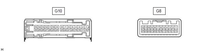
STEREO COMPONENT AMPLIFIER ASSEMBLY (for 14 Speakers)
|
Terminal No. (Symbol) | Wiring Color |
Terminal Description | Condition |
Specified Condition |
|---|---|---|---|---|
|
G10-1 (+B) - G10-3 (GND) |
L - W-B | Power source (+B) |
Power switch off | 11 to 14 V |
|
G10-3 (GND) - Body ground |
W-B - Body ground | Ground |
Always | Below 1 V |
|
G10-5 (WF2+) - G10-3 (GND) |
W - W-B | Sound signal (Woofer) |
Audio system playing |
A waveform synchronized with sound signals is output |
|
G10-6 (WF1+) - G10-3 (GND) |
BE - W-B | Sound signal (Woofer) |
Audio system playing |
A waveform synchronized with sound signals is output |
|
G10-7 (CTR+) - G10-3 (GND) |
SB - W-B | Sound signal (Center) |
Audio system playing |
A waveform synchronized with sound signals is output |
|
G10-8 (TWL+) - G10-3 (GND) |
B - W-B | Sound signal (Front Left) |
Audio system playing |
A waveform synchronized with sound signals is output |
|
G10-9 (TWR+) - G10-3 (GND) |
BE - W-B | Sound signal (Front Right) |
Audio system playing |
A waveform synchronized with sound signals is output |
|
G10-10 (SL+) - G10-3 (GND) |
SB - W-B | Sound signal (Rear Left) |
Audio system playing |
A waveform synchronized with sound signals is output |
|
G10-11 (SR+) - G10-3 (GND) |
B - W-B | Sound signal (Rear Right) |
Audio system playing |
A waveform synchronized with sound signals is output |
|
G10-12 (FL+) - G10-3 (GND) |
LG - W-B | Sound signal (Front Left) |
Audio system playing |
A waveform synchronized with sound signals is output |
|
G10-13 (FR+) - G10-3 (GND) |
W - W-B | Sound signal (Front Right) |
Audio system playing |
A waveform synchronized with sound signals is output |
|
G10-14 (RL+) - G10-3 (GND) |
B - W-B | Sound signal (Rear Left) |
Audio system playing |
A waveform synchronized with sound signals is output |
|
G10-15 (RR+) - G10-3 (GND) |
R - W-B | Sound signal (Rear Right) |
Audio system playing |
A waveform synchronized with sound signals is output |
|
G10-16 (+B2) - G10-3 (GND) |
B - W-B | Power source (+B) |
Power switch off | 11 to 14 V |
|
G10-18 (GND2) - Body ground |
W-B - Body ground | Ground |
Always | Below 1 V |
|
G10-20 (WF2-) - G10-3 (GND) |
R - W-B | Sound signal (Woofer) |
Audio system playing |
A waveform synchronized with sound signals is output |
|
G10-21 (WF1-) - G10-3 (GND) |
L - W-B | Sound signal (Woofer) |
Audio system playing |
A waveform synchronized with sound signals is output |
|
G10-22 (CTR-) - G10-3 (GND) |
W - W-B | Sound signal (Center) |
Audio system playing |
A waveform synchronized with sound signals is output |
|
G10-23 (TWL-) - G10-3 (GND) |
GR - W-B | Sound signal (Front Left) |
Audio system playing |
A waveform synchronized with sound signals is output |
|
G10-24 (TWR-) - G10-3 (GND) |
L - W-B | Sound signal (Front Right) |
Audio system playing |
A waveform synchronized with sound signals is output |
|
G10-25 (SL-) - G10-3 (GND) |
P - W-B | Sound signal (Rear Left) |
Audio system playing |
A waveform synchronized with sound signals is output |
|
G10-26 (SR-) - G10-3 (GND) |
Y - W-B | Sound signal (Rear Right) |
Audio system playing |
A waveform synchronized with sound signals is output |
|
G10-27 (FL-) - G10-3 (GND) |
W - W-B | Sound signal (Front Left) |
Audio system playing |
A waveform synchronized with sound signals is output |
|
G10-28 (FR-) - G10-3 (GND) |
B - W-B | Sound signal (Front Right) |
Audio system playing |
A waveform synchronized with sound signals is output |
|
G10-29 (RL-) - G10-3 (GND) |
LG - W-B | Sound signal (Rear Left) |
Audio system playing |
A waveform synchronized with sound signals is output |
|
G10-30 (RR-) - G10-3 (GND) |
W - W-B | Sound signal (Rear Right) |
Audio system playing |
A waveform synchronized with sound signals is output |
|
G8-1 (MUTE) - G10-3 (GND) |
BE - W-B |
Mute signal | Power switch on (ACC) Audio system playing |
2.0 V or higher |
|
Audio system changing modes |
Below 1 V | |||
|
G8-2 (L-) - G10-3 (GND) |
G - W-B | Sound signal (Left) |
Audio system playing |
A waveform synchronized with sound signals is output |
|
G8-3 (L+) - G10-3 (GND) |
B - W-B | Sound signal (Left) |
Audio system playing |
A waveform synchronized with sound signals is output |
|
G8-4 (R-) - G10-3 (GND) |
R - W-B | Sound signal (Right) |
Audio system playing |
A waveform synchronized with sound signals is output |
|
G8-5 (R+) - G10-3 (GND) |
W - W-B | Sound signal (Right) |
Audio system playing |
A waveform synchronized with sound signals is output |
|
G8-6 (SLD) - Body ground |
Shield - Body ground |
Shield ground | Always |
Below 1 V |
|
G8-7 (TX-) | W |
AVC-LAN communication signal |
- | - |
|
G8-8 (TX+) | B |
AVC-LAN communication signal |
- | - |
|
G8-11 (SPD) - G10-3 (GND) |
G - W-B | Vehicle speed signal |
Power switch on (IG) Wheel being rotated |
Pulse generation |
|
G8-12 (ACC) - G10-3 (GND) |
P - W-B | Power source (ACC) |
Power switch off | Below 1 V |
|
Power switch on (ACC) |
11 to 14 V | |||
|
G8-14 (II1-) - G10-3 (GND) |
BR - W-B | Voice signal |
Voice guidance sounding |
A waveform synchronized with voice signals is output |
|
G8-15 (II1+) - G10-3 (GND) |
Y - W-B | Voice signal |
Voice guidance sounding |
A waveform synchronized with voice signals is output |
|
G8-18 (SLD1) - Body ground |
Shield - Body ground |
Shield ground | Always |
Below 1 V |
|
G8-24 (TMUT) - Body ground |
BE - Body ground |
Mute signal | Power switch on (ACC) Audio system playing |
2.0 V or higher |
|
Emergency call mode | Below 1 V |
DCM (TELEMATICS TRANSCEIVER)
Click here

COMBINATION METER ASSEMBLY
Click here
PARKING BRAKE ECU (BRAKE ACTUATOR ASSEMBLY)
Click here
Toyota Avalon (XX50) 2019-2022 Service & Repair Manual > Smart Key System(for Start Function, Gasoline Model): Lost Communication with ECM / PCM (U0100,U0140,U0142,U0155). Unable to Unlock Steering Wheel (Engine cannot Start)
Lost Communication with ECM / PCM (U0100,U0140,U0142,U0155) DESCRIPTION These DTCs are stored when there is a CAN communication malfunction between the certification ECU (smart key ECU assembly), ECM, main body ECU (multiplex network body ECU) or combination meter assembly, and data from the option ...


