Stereo Component Amplifier Disconnected (B15D3)
DESCRIPTION
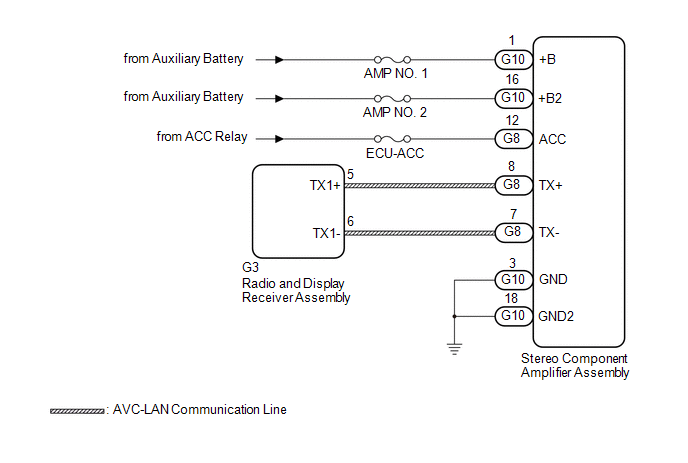
The radio and display receiver assembly and stereo component amplifier assembly are connected via AVC-LAN communication line.
|
DTC No. | Detection Item |
DTC Detection Condition | Trouble Area |
|
B15D3 | Stereo Component Amplifier Disconnected |
When either of the following conditions is met:
- Stereo component amplifier assembly is/was not connected while the power switch is/was on (IG) or on (ACC)
- Communication between the master unit and the stereo component amplifier assembly is not possible when the engine is started.
|
- Stereo component amplifier assembly power source circuit
- AVC-LAN circuit between radio and display receiver assembly and stereo component amplifier assembly
- Stereo component amplifier assembly
- Radio and display receiver assembly
- Harness or connector
|
HINT:
The radio and display receiver assembly is the master unit.
WIRING DIAGRAM
CAUTION / NOTICE / HINT
NOTICE:
- Inspect the fuses for circuits related to this system before performing the following procedure.
- Depending on the parts that are replaced during vehicle inspection or
maintenance, performing initialization, registration or calibration may
be needed. Refer to Precaution for Audio and Visual System.
Click here 
- When replacing the radio and display receiver assembly, always replace
it with a new one. If a radio and display receiver assembly which was
installed to another vehicle is used, the following may occur:
- A communication malfunction DTC may be stored.
- The radio and display receiver assembly may not operate normally.
PROCEDURE
(a) If DTC B15C3 is output, perform troubleshooting for DTC B15C3 first.
|
Result | Proceed to |
|
DTC B15C3 is not output. |
A |
| DTC B15C3 is output. |
B |
| B |
 | GO TO DTC B15C3 |
|
A |
 | |
| 2. |
CHECK OPTIONAL COMPONENTS (INCLUDING ASSOCIATED WIRING) |
(a) Check that optional components (including associated wiring) which generate radio waves are not installed.
|
Result | Proceed to |
|
Optional components (including associated wiring) are installed. |
A |
| Optional components (including associated wiring) are not installed. |
B |
HINT:
- Electrical noise from radio waves generated by optional components or
the wiring for those components may affect AVC-LAN communication.
- This DTC may be stored when an AVC-LAN communication error occurs due to electrical noise.
| B |
| GO TO STEP 4 |
|
A | |
| |
| 3. |
REMOVE OPTIONAL COMPONENTS (INCLUDING ASSOCIATED WIRING) |
(a) Remove optional components (including associated wiring).
NOTICE:
Do not remove optional components or associated wiring without the permission of the customer.
|
NEXT | |
| |
(a) Clear the DTCs.
Body Electrical > Navigation System > Clear DTCs
(b) Recheck for DTCs and check that no DTCs are output.
Body Electrical > Navigation System > Trouble Codes
OK:
No DTCs are output.
| OK | |
END |
|
NG | |
| |
| 5. |
CHECK HARNESS AND CONNECTOR (STEREO COMPONENT AMPLIFIER ASSEMBLY POWER SOURCE) |
(a) Disconnect the G10 and G8 stereo component amplifier assembly connectors.
(b) Measure the resistance according to the value(s) in the table below.
Standard Resistance:
|
Tester Connection | Condition |
Specified Condition |
|
G10-3 (GND) - Body ground |
Always | Below 1 Ω |
|
G10-18 (GND2) - Body ground |
Always | Below 1 Ω |
(c) Measure the voltage according to the value(s) in the table below.
Standard Voltage:
|
Tester Connection | Condition |
Specified Condition |
|
G10-1 (+B) - G10-3 (GND) |
Power switch off | 11 to 14 V |
|
G10-16 (+B2) - G10-3 (GND) |
Power switch off | 11 to 14 V |
|
G8-12 (ACC) - G10-3 (GND) |
Power switch on (ACC) |
11 to 14 V |
| NG |
| REPAIR OR REPLACE HARNESS OR CONNECTOR |
|
OK | |
| |
| 6. |
CHECK HARNESS AND CONNECTOR (RADIO AND DISPLAY RECEIVER ASSEMBLY - STEREO COMPONENT AMPLIFIER ASSEMBLY) |
(a) Disconnect the G3 radio and display receiver assembly connector.
(b) Disconnect the G8 stereo component amplifier assembly connector.
(c) Measure the resistance according to the value(s) in the table below.
Standard Resistance:
|
Tester Connection | Condition |
Specified Condition |
|
G3-5 (TX1+) - G8-8 (TX+) |
Always | Below 1 Ω |
|
G3-6 (TX1-) - G8-7 (TX-) |
Always | Below 1 Ω |
|
G3-5 (TX1+) or G8-8 (TX+) - Body ground |
Always | 10 kΩ or higher |
|
G3-6 (TX1-) or G8-7 (TX-) - Body ground |
Always | 10 kΩ or higher |
| NG |
| REPAIR OR REPLACE HARNESS OR CONNECTOR |
|
OK | |
| |
| 7. |
REPLACE STEREO COMPONENT AMPLIFIER ASSEMBLY |
(a) Replace the stereo component amplifier assembly with a new or known good one.
Click here
(b) Clear the DTCs.
Body Electrical > Navigation System > Clear DTCs
(c) Recheck for DTCs and check that no DTCs are output.
Body Electrical > Navigation System > Trouble Codes
OK:
No DTCs are output.
| OK | |
END |
| NG |
| REPLACE RADIO AND DISPLAY RECEIVER ASSEMBLY |
Telematics Transceiver Disconnected (B15DB)
DESCRIPTION
If the radio
and display receiver assembly cannot detect the DCM (telematics
transceiver) for a certain period of time (90 seconds) after the power
switch is turned on (ACC) and the radio and display receiver assembly
confirms that the information is missing by checking past DCM
(telematics transceiver) recognition information (registered
information), this DTC will be stored.
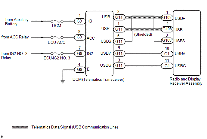
The
telematics system uses USB communication between devices. If an open,
short, short to +B or short to ground occurs in the USB circuit,
communication is interrupted and the telematics system will not operate
normally.
|
DTC No. | Detection Item |
DTC Detection Condition | Trouble Area |
|
B15DB | Telematics Transceiver Disconnected |
DCM (telematics transceiver) disconnected |
- Harness or connector
- DCM (telematics transceiver)
- DCM (telematics transceiver) power source circuit
- Radio and display receiver assembly
|
HINT:
This DTC may be stored due to environmental reasons such as electrical noise or interference.
WIRING DIAGRAM
CAUTION / NOTICE / HINT
NOTICE:
- Depending on the parts that are replaced during vehicle inspection or
maintenance, performing initialization, registration or calibration may
be needed. Refer to Precaution for Audio and Visual System.
Click here 
- When replacing the radio and display receiver assembly, always replace
it with a new one. If a radio and display receiver assembly which was
installed to another vehicle is used, the following may occur:
- A communication malfunction DTC may be stored.
- The radio and display receiver assembly may not operate normally.
- Inspect the fuses for circuits related to this system before performing the following procedure.
- Before replacing the DCM (telematics transceiver), refer to Registration.
Click here
PROCEDURE
|
1. | CHECK HARNESS AND CONNECTOR (DCM (TELEMATICS TRANSCEIVER) POWER SOURCE) |
(a) Disconnect the G9 DCM (telematics transceiver) connector.
(b) Measure the resistance according to the value(s) in the table below.
Standard Resistance:
|
Tester Connection | Condition |
Specified Condition |
|
G9-4 (E) - Body ground |
Always | Below 1 Ω |
(c) Measure the voltage according to the value(s) in the table below.
Standard Voltage:
|
Tester Connection | Condition |
Specified Condition |
|
G9-1 (+B) - G9-4 (E) |
Power switch off | 11 to 14 V |
|
G9-8 (ACC) - G9-4 (E) |
Power switch on (ACC) |
11 to 14 V |
|
G9-7 (IG2) - G9-4 (E) |
Power switch on (IG) |
11 to 14 V |
| NG |
 | REPAIR OR REPLACE HARNESS OR CONNECTOR |
|
OK |
 | |
| 2. |
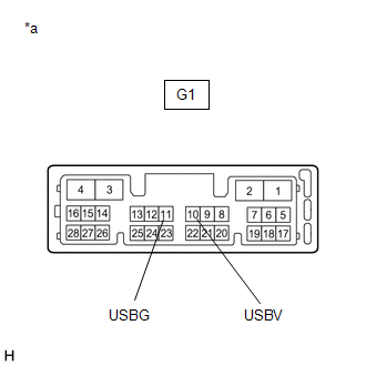
INSPECT RADIO AND DISPLAY RECEIVER ASSEMBLY |
(a) Disconnect the G1 radio and display receiver assembly connector.
| (b) Measure the resistance according to the value(s) in the table below.
Standard Resistance: |
Tester Connection | Condition |
Specified Condition | |
G1-11 (USBG) - Body ground |
Always | Below 1 Ω | |
 |
|
*a | Component without harness connected
(Radio and Display Receiver Assembly) | | |
(c) Measure the voltage according to the value(s) in the table below.
Standard Voltage:
|
Tester Connection | Condition |
Specified Condition |
|
G1-10 (USBV) - G1-11 (USBG) |
Power switch on (IG) |
4.75 to 5.25 V |
| NG |
| REPLACE RADIO AND DISPLAY RECEIVER ASSEMBLY |
|
OK | |
| |
| 3. |
CHECK HARNESS AND CONNECTOR (RADIO AND DISPLAY RECEIVER ASSEMBLY - DCM (TELEMATICS TRANSCEIVER)) |
(a) Disconnect the G1 radio and display receiver assembly connector.
(b) Disconnect the G11 DCM (telematics transceiver) connector.
(c) Measure the resistance according to the value(s) in the table below.
Standard Resistance:
|
Tester Connection | Condition |
Specified Condition |
|
G1-10 (USBV) - G11-5 (USBV) |
Always | Below 1 Ω |
|
G1-11 (USBG) - G11-3 (USBG) |
Always | Below 1 Ω |
|
G1-10 (USBV) or G11-5 (USBV) - Body ground |
Always | 10 kΩ or higher |
|
G1-11 (USBG) or G11-3 (USBG) - Body ground |
Always | 10 kΩ or higher |
| NG |
| REPAIR OR REPLACE HARNESS OR CONNECTOR |
|
OK | |
| |
| 4. |
CHECK HARNESS AND CONNECTOR (RADIO AND DISPLAY RECEIVER ASSEMBLY - DCM (TELEMATICS TRANSCEIVER)) |
(a) Check the installation condition.
(1)
Check the USB communication lines between the radio and display
receiver assembly and DCM (telematics transceiver) for any installation
or connection problems.
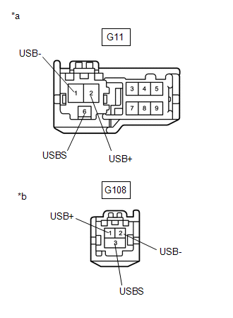
(b) Disconnect the G108 radio and display receiver assembly connector.
(c) Disconnect the G11 DCM (telematics transceiver) connector.
| (d) Measure the resistance according to the value(s) in the table below.
Standard Resistance: |
Tester Connection | Condition |
Specified Condition | |
G108-1 (USB+) - G11-2 (USB+) |
Always | Below 1 Ω | |
G108-2 (USB-) - G11-1 (USB-) |
Always | Below 1 Ω | |
G108-3 (USBS) - G11-6 (USBS) |
Always | Below 1 Ω | |
G108-1 (USB+) or G11-2 (USB+) - Body ground |
Always | 10 kΩ or higher | |
G108-2 (USB-) or G11-1 (USB-) - Body ground |
Always | 10 kΩ or higher | |
G108-3 (USBS) or G11-6 (USBS) - Body ground |
Always | 10 kΩ or higher | |
 |
|
*a | Front view of wire harness connector
(to DCM (Telematics Transceiver)) | |
*b | Front view of wire harness connector
(to Radio and Display Receiver Assembly) | | |
| NG |
| REPAIR OR REPLACE HARNESS OR CONNECTOR |
|
OK | |
| |
| 5. |
REPLACE DCM (TELEMATICS TRANSCEIVER) |
(a) Replace the DCM (telematics transceiver) with a new one.
Click here
(b) Clear the DTCs.
Body Electrical > Navigation System > Clear DTCs
(c) Turn the power switch off.
(d) Turn the power switch on (IG) and wait for 90 seconds.
(e) Recheck for DTCs and check that no DTCs are output.
Body Electrical > Navigation System > Trouble Codes
OK:
No DTCs are output.
| OK | |
END |
| NG |
| REPLACE RADIO AND DISPLAY RECEIVER ASSEMBLY |
Air Conditioner ECU Vehicle Information Reading/Writing Processor Malfunction (B15F5)
DESCRIPTION
This DTC is
stored when items controlled by the air conditioning amplifier assembly
cannot be customized via the audio and visual system vehicle
customization screen.
HINT:
The
air conditioning amplifier assembly controls the air conditioning
system related items that are customizable via the audio and visual
system vehicle customization screen.
|
DTC No. | Detection Item |
DTC Detection Condition | Trouble Area |
|
B15F5 | Air Conditioner ECU Vehicle Information Reading/Writing Processor Malfunction |
Air conditioning amplifier assembly vehicle setting processing malfunction |
- CAN communication system
- Air conditioning system
- Air conditioning amplifier assembly
- Radio and display receiver assembly
|
CAUTION / NOTICE / HINT
NOTICE:
- Depending on the parts that are replaced during vehicle inspection or
maintenance, performing initialization, registration or calibration may
be needed. Refer to Precaution for Audio and Visual System.
Click here 
- When replacing the radio and display receiver assembly, always replace
it with a new one. If a radio and display receiver assembly which was
installed to another vehicle is used, the following may occur:
- A communication malfunction DTC may be stored.
- The radio and display receiver assembly may not operate normally.
PROCEDURE
|
1. | CHECK CAN COMMUNICATION SYSTEM |
(a) Use the Techstream to check if the CAN communication system is functioning normally.
Click here
OK:
CAN communication DTCs are not output.
| NG |
 | GO TO CAN COMMUNICATION SYSTEM |
|
OK |
 | |
| 2. |
CHECK AIR CONDITIONING SYSTEM |
(a) Check if the air conditioning system is malfunctioning.
Click here
HINT:
Customization may not be possible depending on the malfunction in the air conditioning system.
OK:
No malfunctions are present in the air conditioning system.
| NG |
| GO TO AIR CONDITIONING SYSTEM |
|
OK | |
| |
(a) Make a note of the customizable items for the air conditioning system.
HINT:
The
items shown as customizable via the audio and visual system vehicle
customization screen can also be changed using the Techstream. In the
following step, the Techstream will be used.
(1) To
match-up the items on the audio and visual system vehicle customization
screen with the items on the Techstream, check the customize parameters
list for the air conditioning system related items that can be
customized via the audio and visual system vehicle customization screen.
Click here
(b)
Using the Techstream, check that it is possible to change the settings
of the customize parameters that are available for customization via the
audio and visual system vehicle customization screen.
OK:
The
items available for customization via the audio and visual system
vehicle customization screen can be customized successfully using the
Techstream.
| OK |
| REPLACE RADIO AND DISPLAY RECEIVER ASSEMBLY |
| NG |
| REPLACE AIR CONDITIONING AMPLIFIER ASSEMBLY |


