DESCRIPTION
This DTC is stored when a malfunction occurs in the speakers.
|
DTC No. | Detection Item |
DTC Detection Condition | Trouble Area |
|---|---|---|---|
|
B15C3 | Speaker Output Short |
A short is detected in the speaker output circuit |
|
WIRING DIAGRAM
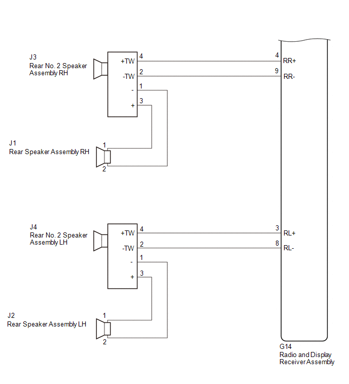
for 8 Speakers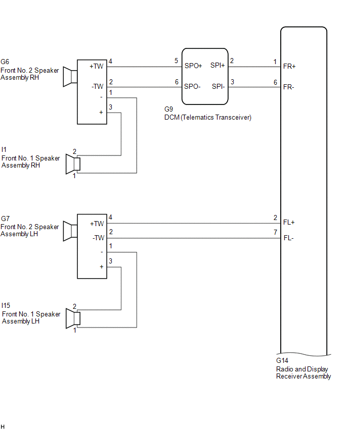
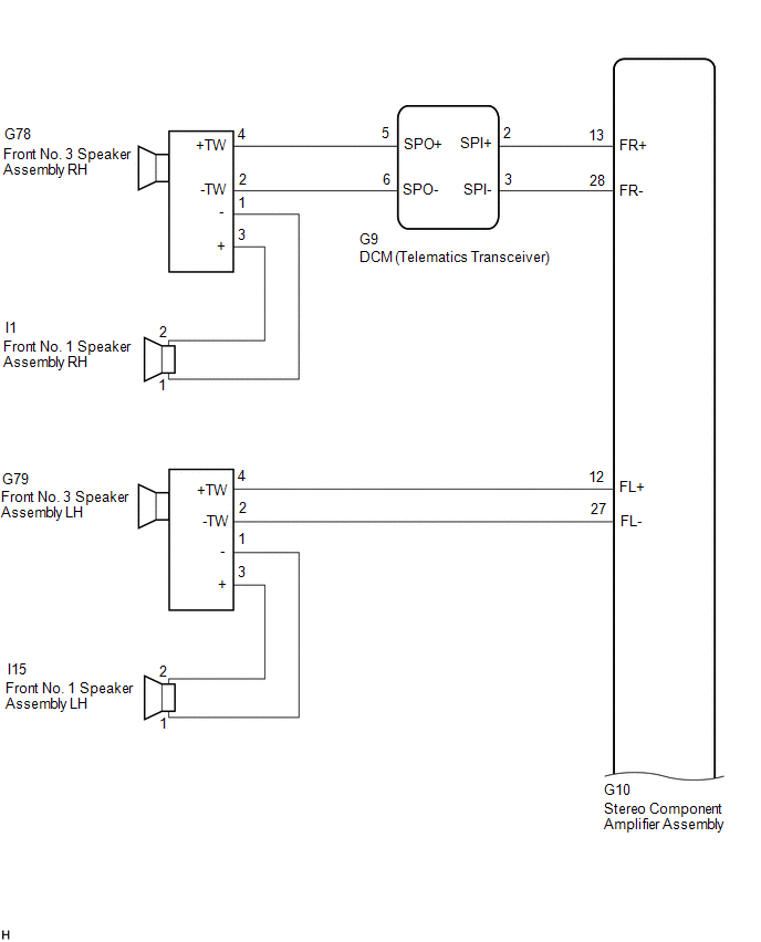
 for 14 Speakers
CAUTION / NOTICE / HINT
NOTICE:
Click here 
Click here
PROCEDURE
|
1. | CHECK MODEL |
(a) Choose the model to be inspected.
|
Result | Proceed to |
|---|---|
|
for 8 Speakers | A |
|
for 14 Speakers | B |
| B |
 | GO TO STEP 11 |
|
| 2. |
CHECK HARNESS AND CONNECTOR (RADIO AND DISPLAY RECEIVER ASSEMBLY, DCM (TELEMATICS TRANSCEIVER) OR SPEAKERS - BODY GROUND) |
(a) Disconnect the G14 radio and display receiver assembly connector.
(b) Disconnect the G9 DCM (telematics transceiver) connector.
(c) Disconnect the G7 front No. 2 speaker assembly LH connector.
(d) Disconnect the J3 and J4 rear No. 2 speaker assembly connectors.
(e) Measure the resistance according to the value(s) in the table below.
Standard Resistance:
|
Tester Connection | Condition |
Specified Condition |
|---|---|---|
|
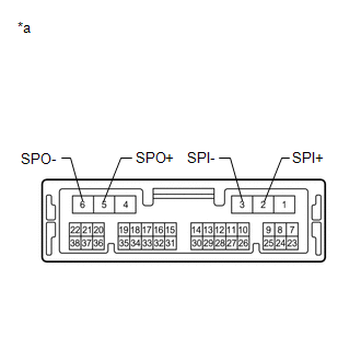
G14-1 (FR+) or G9-2 (SPI+) - Body ground |
Always | 10 kΩ or higher |
|
G14-6 (FR-) or G9-3 (SPI-) - Body ground |
Always | 10 kΩ or higher |
|
G14-2 (FL+) or G7-4 (+TW) - Body ground |
Always | 10 kΩ or higher |
|
G14-7 (FL-) or G7-2 (-TW) - Body ground |
Always | 10 kΩ or higher |
|
G14-4 (RR+) or J3-4 (+TW) - Body ground |
Always | 10 kΩ or higher |
|
G14-9 (RR-) or J3-2 (-TW) - Body ground |
Always | 10 kΩ or higher |
|
G14-3 (RL+) or J4-4 (+TW) - Body ground |
Always | 10 kΩ or higher |
|
G14-8 (RL-) or J4-2 (-TW) - Body ground |
Always | 10 kΩ or higher |
| NG | | REPAIR OR REPLACE HARNESS OR CONNECTOR |
|
| 3. |
CHECK HARNESS AND CONNECTOR (DCM (TELEMATICS TRANSCEIVER) OR SPEAKER - BODY GROUND) |
(a) Disconnect the G9 DCM (telematics transceiver) connector.
(b) Disconnect the G6 front No. 2 speaker assembly RH connector.
(c) Measure the resistance according to the value(s) in the table below.
Standard Resistance:
|
Tester Connection | Condition |
Specified Condition |
|---|---|---|
|
G9-5 (SPO+) or G6-4 (+TW) - Body ground |
Always | 10 kΩ or higher |
|
G9-6 (SPO-) or G6-2 (-TW) - Body ground |
Always | 10 kΩ or higher |
| NG | | REPAIR OR REPLACE HARNESS OR CONNECTOR |
|
| 4. |
INSPECT DCM (TELEMATICS TRANSCEIVER) |
(a) Remove the DCM (telematics transceiver).
Click here
| (b) Measure the resistance according to the value(s) in the table below. Standard Resistance:
|
|
| NG | | REPLACE DCM (TELEMATICS TRANSCEIVER) |
|
| 5. |
CHECK HARNESS AND CONNECTOR (FRONT NO. 1 SPEAKER ASSEMBLY OR FRONT NO. 2 SPEAKER ASSEMBLY - BODY GROUND) |
(a) Disconnect the I1 and I15 front No. 1 speaker assembly connectors.
(b) Disconnect the G6 and G7 front No. 2 speaker assembly connectors.
(c) Measure the resistance according to the value(s) in the table below.
Standard Resistance:
|
Tester Connection | Condition |
Specified Condition |
|---|---|---|
|
I1-2 or G6-3 (+) - Body ground |
Always | 10 kΩ or higher |
|
I1-1 or G6-1 (-) - Body ground |
Always | 10 kΩ or higher |
|
I15-2 or G7-3 (+) - Body ground |
Always | 10 kΩ or higher |
|
I15-1 or G7-1 (-) - Body ground |
Always | 10 kΩ or higher |
| NG | | REPAIR OR REPLACE HARNESS OR CONNECTOR |
|
| 6. |
CHECK HARNESS AND CONNECTOR (REAR SPEAKER ASSEMBLY OR REAR NO. 2 SPEAKER ASSEMBLY - BODY GROUND) |
(a) Disconnect the J1 and J2 rear speaker assembly connectors.
(b) Disconnect the J3 and J4 rear No. 2 speaker assembly connectors.
(c) Measure the resistance according to the value(s) in the table below.
Standard Resistance:
|
Tester Connection | Condition |
Specified Condition |
|---|---|---|
|
J1-1 or J3-3 (+) - Body ground |
Always | 10 kΩ or higher |
|
J1-2 or J3-1 (-) - Body ground |
Always | 10 kΩ or higher |
|
J2-1 or J4-3 (+) - Body ground |
Always | 10 kΩ or higher |
|
J2-2 or J4-1 (-) - Body ground |
Always | 10 kΩ or higher |
| NG | | REPAIR OR REPLACE HARNESS OR CONNECTOR |
|
| 7. |
INSPECT FRONT NO. 1 SPEAKER ASSEMBLY |
(a) Remove the front No. 1 speaker assembly.
Click here
(b) Inspect the front No. 1 speaker assembly.
Click here
| NG | | REPLACE FRONT NO. 1 SPEAKER ASSEMBLY |
|
| 8. |
INSPECT REAR SPEAKER ASSEMBLY |
(a) Remove the rear speaker assembly.
Click here
(b) Inspect the rear speaker assembly.
Click here
| NG | | REPLACE REAR SPEAKER ASSEMBLY |
|
| 9. |
REPLACE FRONT NO. 2 SPEAKER ASSEMBLY |
(a) Remove the front No. 2 speaker assembly.
Click here
(b) Inspect the front No. 2 speaker assembly.
Click here
(c) Clear the DTCs.
Body Electrical > Navigation System > Clear DTCs(d) Recheck for DTCs and check that no DTCs are output.
Body Electrical > Navigation System > Trouble CodesOK:
No DTCs are output.
| OK | |
END |
|
| 10. |
REPLACE REAR NO. 2 SPEAKER ASSEMBLY |
(a) Remove the rear No. 2 speaker assembly.
Click here
(b) Inspect the rear No. 2 speaker assembly.
Click here
(c) Clear the DTCs.
Body Electrical > Navigation System > Clear DTCs(d) Recheck for DTCs and check that no DTCs are output.
Body Electrical > Navigation System > Trouble CodesOK:
No DTCs are output.
| OK | |
END |
| NG | | REPLACE RADIO AND DISPLAY RECEIVER ASSEMBLY |
| 11. |
CHECK HARNESS AND CONNECTOR (STEREO COMPONENT AMPLIFIER ASSEMBLY, DCM (TELEMATICS TRANSCEIVER) OR SPEAKERS - BODY GROUND) |
(a) Disconnect the G10 stereo component amplifier assembly connector.
(b) Disconnect the G9 DCM (telematics transceiver) connector.
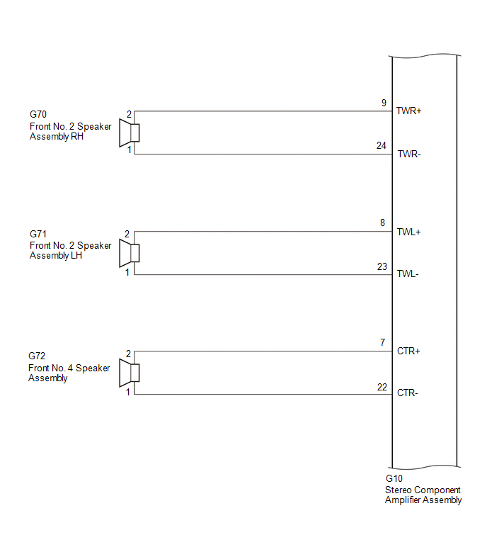
(c) Disconnect the G70 and G71 front No. 2 speaker assembly connectors.
(d) Disconnect the G72 front No. 4 speaker assembly connector.
(e) Disconnect the G79 front No. 3 speaker assembly LH connector.
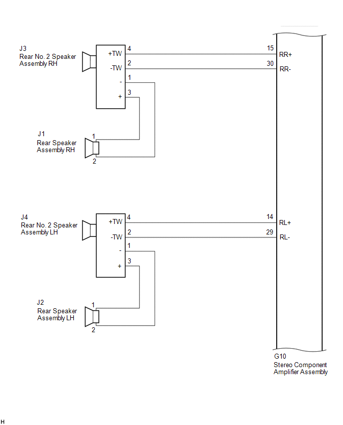
(f) Disconnect the J3 and J4 rear No. 2 speaker assembly connectors.
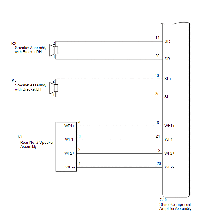
(g) Disconnect the K2 and K3 speaker assembly with bracket connectors.
(h) Disconnect the K1 rear No. 3 speaker assembly connector.
(i) Measure the resistance according to the value(s) in the table below.
Standard Resistance:
|
Tester Connection | Condition |
Specified Condition |
|---|---|---|
|
G10-9 (TWR+) or G70-2 - Body ground |
Always | 10 kΩ or higher |
|
G10-24 (TWR-) or G70-1 - Body ground |
Always | 10 kΩ or higher |
|
G10-8 (TWL+) or G71-2 - Body ground |
Always | 10 kΩ or higher |
|
G10-23 (TWL-) or G71-1 - Body ground |
Always | 10 kΩ or higher |
|
G10-13 (FR+) or G9-2 (SPI+) - Body ground |
Always | 10 kΩ or higher |
|
G10-28 (FR-) or G9-3 (SPI-) - Body ground |
Always | 10 kΩ or higher |
|
G10-12 (FL+) or G79-4 (+TW) - Body ground |
Always | 10 kΩ or higher |
|
G10-27 (FL-) or G79-2 (-TW) - Body ground |
Always | 10 kΩ or higher |
|
G10-15 (RR+) or J3-4 (+TW) - Body ground |
Always | 10 kΩ or higher |
|
G10-30 (RR-) or J3-2 (-TW) - Body ground |
Always | 10 kΩ or higher |
|
G10-14 (RL+) or J4-4 (+TW) - Body ground |
Always | 10 kΩ or higher |
|
G10-29 (RL-) or J4-2 (-TW) - Body ground |
Always | 10 kΩ or higher |
|
G10-6 (WF1+) or K1-4 (WF1+) - Body ground |
Always | 10 kΩ or higher |
|
G10-21 (WF1-) or K1-3 (WF1-) - Body ground |
Always | 10 kΩ or higher |
|
G10-5 (WF2+) or K1-2 (WF2+) - Body ground |
Always | 10 kΩ or higher |
|
G10-20 (WF2-) or K1-1 (WF2-) - Body ground |
Always | 10 kΩ or higher |
|
G10-7 (CTR+) or G72-2 - Body ground |
Always | 10 kΩ or higher |
|
G10-22 (CTR-) or G72-1 - Body ground |
Always | 10 kΩ or higher |
|
G10-11 (SR+) or K2-2 - Body ground |
Always | 10 kΩ or higher |
|
G10-26 (SR-) or K2-1 - Body ground |
Always | 10 kΩ or higher |
|
G10-10 (SL+) or K3-2 - Body ground |
Always | 10 kΩ or higher |
|
G10-25 (SL-) or K3-1 - Body ground |
Always | 10 kΩ or higher |
| NG | | REPAIR OR REPLACE HARNESS OR CONNECTOR |
|
| 12. |
CHECK HARNESS AND CONNECTOR (DCM (TELEMATICS TRANSCEIVER) OR SPEAKER - BODY GROUND) |
(a) Disconnect the G9 DCM (telematics transceiver) connector.
(b) Disconnect the G78 front No. 3 speaker assembly RH connector.
(c) Measure the resistance according to the value(s) in the table below.
Standard Resistance:
|
Tester Connection | Condition |
Specified Condition |
|---|---|---|
|
G9-5 (SPO+) or G78-4 (+TW) - Body ground |
Always | 10 kΩ or higher |
|
G9-6 (SPO-) or G78-2 (-TW) - Body ground |
Always | 10 kΩ or higher |
| NG | | REPAIR OR REPLACE HARNESS OR CONNECTOR |
|
| 13. |
INSPECT DCM (TELEMATICS TRANSCEIVER) |
(a) Remove the DCM (telematics transceiver).
Click here
| (b) Measure the resistance according to the value(s) in the table below. Standard Resistance:
|
|
| NG | | REPLACE DCM (TELEMATICS TRANSCEIVER) |
|
| 14. |
CHECK HARNESS AND CONNECTOR (FRONT NO. 1 SPEAKER ASSEMBLY OR FRONT NO. 3 SPEAKER ASSEMBLY - BODY GROUND) |
(a) Disconnect the I1 and I15 front No. 1 speaker assembly connectors.
(b) Disconnect the G78 and G79 front No. 3 speaker assembly connectors.
(c) Measure the resistance according to the value(s) in the table below.
Standard Resistance:
|
Tester Connection | Condition |
Specified Condition |
|---|---|---|
|
I1-2 or G78-3 (+) - Body ground |
Always | 10 kΩ or higher |
|
I1-1 or G78-1 (-) - Body ground |
Always | 10 kΩ or higher |
|
I15-2 or G79-3 (+) - Body ground |
Always | 10 kΩ or higher |
|
I15-1 or G79-1 (-) - Body ground |
Always | 10 kΩ or higher |
| NG | | REPAIR OR REPLACE HARNESS OR CONNECTOR |
|
| 15. |
CHECK HARNESS AND CONNECTOR (REAR SPEAKER ASSEMBLY OR REAR NO. 2 SPEAKER ASSEMBLY - BODY GROUND) |
(a) Disconnect the J1 and J2 rear speaker assembly connectors.
(b) Disconnect the J3 and J4 rear No. 2 speaker assembly connectors.
(c) Measure the resistance according to the value(s) in the table below.
Standard Resistance:
|
Tester Connection | Condition |
Specified Condition |
|---|---|---|
|
J1-1 or J3-3 (+) - Body ground |
Always | 10 kΩ or higher |
|
J1-2 or J3-1 (-) - Body ground |
Always | 10 kΩ or higher |
|
J2-1 or J4-3 (+) - Body ground |
Always | 10 kΩ or higher |
|
J2-2 or J4-1 (-) - Body ground |
Always | 10 kΩ or higher |
| NG | | REPAIR OR REPLACE HARNESS OR CONNECTOR |
|
| 16. |
INSPECT FRONT NO. 1 SPEAKER ASSEMBLY |
(a) Remove the front No. 1 speaker assembly.
Click here
(b) Inspect the front No. 1 speaker assembly.
Click here
| NG | | REPLACE FRONT NO. 1 SPEAKER ASSEMBLY |
|
| 17. |
INSPECT FRONT NO. 2 SPEAKER ASSEMBLY |
(a) Remove the front No. 2 speaker assembly.
Click here
(b) Inspect the front No. 2 speaker assembly.
Click here
| NG | | REPLACE FRONT NO. 2 SPEAKER ASSEMBLY |
|
| 18. |
INSPECT FRONT NO. 4 SPEAKER ASSEMBLY |
(a) Remove the front No. 4 speaker assembly.
Click here
(b) Inspect the front No. 4 speaker assembly.
Click here
| NG | | REPLACE FRONT NO. 4 SPEAKER ASSEMBLY |
|
| 19. |
INSPECT REAR SPEAKER ASSEMBLY |
(a) Remove the rear speaker assembly.
Click here
(b) Inspect the rear speaker assembly.
Click here
| NG | | REPLACE REAR SPEAKER ASSEMBLY |
|
| 20. |
INSPECT SPEAKER ASSEMBLY WITH BRACKET |
(a) Remove the speaker assembly with bracket.
Click here
(b) Inspect the speaker assembly with bracket.
Click here
| NG | | REPLACE SPEAKER ASSEMBLY WITH BRACKET |
|
| 21. |
INSPECT REAR NO. 3 SPEAKER ASSEMBLY |
(a) Remove the rear No. 3 speaker assembly.
Click here
(b) Inspect the rear No. 3 speaker assembly.
Click here
| NG | | REPLACE REAR NO. 3 SPEAKER ASSEMBLY |
|
| 22. |
REPLACE FRONT NO. 3 SPEAKER ASSEMBLY |
(a) Remove the front No. 3 speaker assembly.
Click here
(b) Inspect the front No. 3 speaker assembly.
Click here
(c) Clear the DTCs.
Body Electrical > Navigation System > Clear DTCs(d) Recheck for DTCs and check that no DTCs are output.
Body Electrical > Navigation System > Trouble CodesOK:
No DTCs are output.
| OK | |
END |
|
| 23. |
REPLACE REAR NO. 2 SPEAKER ASSEMBLY |
(a) Remove the rear No. 2 speaker assembly.
Click here
(b) Inspect the rear No. 2 speaker assembly.
Click here
(c) Clear the DTCs.
Body Electrical > Navigation System > Clear DTCs(d) Recheck for DTCs and check that no DTCs are output.
Body Electrical > Navigation System > Trouble CodesOK:
No DTCs are output.
| OK | |
END |
| NG | | REPLACE STEREO COMPONENT AMPLIFIER ASSEMBLY |
Toyota Avalon (XX50) 2019-2022 Service & Repair Manual > A25a-fxs (emission Control): Purge Valve
ComponentsCOMPONENTS ILLUSTRATION *1 PURGE VALVE (PURGE VSV) *2 NO. 1 FUEL VAPOR FEED HOSE *3 NO. 2 FUEL VAPOR FEED HOSE - - N*m (kgf*cm, ft.*lbf): Specified torque - - InspectionINSPECTION PROCEDURE 1. INSPECT PURGE VALVE (PURGE VSV) (a) Measure the resistance according to the value(s) in the tabl ...