ANC ECU EEPROM Data Memory Failure (B1AA044)
DESCRIPTION
This DTC are stored when a malfunction occurs in the stereo component equalizer assembly.
|
DTC No. | Detection Item |
DTC Detection Condition | Trouble Area |
|
B1AA044 | ANC ECU EEPROM Data Memory Failure |
Stereo component equalizer assembly malfunction |
Stereo component equalizer assembly |
PROCEDURE
(a) Clear the DTCs.
Body Electrical > Active Noise Control > Clear DTCs
|
NEXT |
 | |
(a) Check for DTCs.
Body Electrical > Active Noise Control > Trouble Codes
OK:
DTC B1AA044 is not output.
| OK |
 | USE SIMULATION METHOD TO CHECK |
| NG |
| REPLACE STEREO COMPONENT EQUALIZER ASSEMBLY |
UART Communication Between ANC and Audio Amplifier Missing Message (B1AA187)
DESCRIPTION
This DTC is
stored when an UART communication error occurs between the stereo
component equalizer assembly and stereo component amplifier assembly.
|
DTC No. | Detection Item |
DTC Detection Condition | Trouble Area |
|
B1AA187 | UART Communication Between ANC and Audio Amplifier Missing Message |
Stereo
component equalizer assembly detects a UART communication malfunction
in stereo component amplifier assembly for 4 seconds or more
continuously* |
- Harness or connector
- Stereo component amplifier assembly
- Stereo component equalizer assembly
|
HINT:
*: Malfunction monitoring is not performed under the following conditions, in order to prevent erroneous detection.
- After engine switch is turned on (ACC) for 3 seconds or more.
- After the battery voltage returns to normal for 3 seconds.
- Before 3 seconds have elapsed after battery voltage has returned to normal.
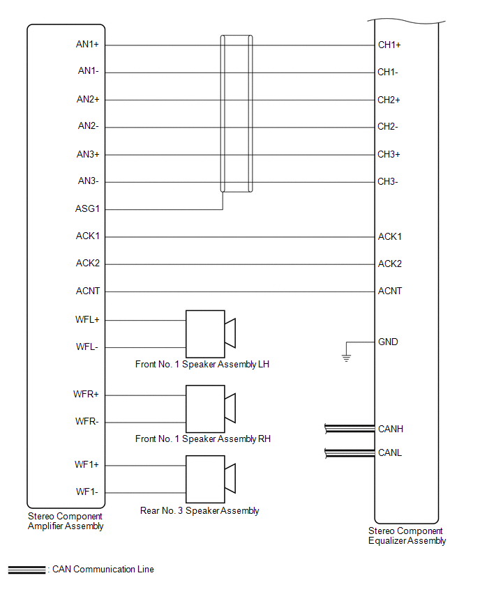
WIRING DIAGRAM
PROCEDURE
(a) Clear the DTCs.
Body Electrical > Active Noise Control > Clear DTCs
|
NEXT |
 | |
(a) Check for DTCs.
Body Electrical > Active Noise Control > Trouble Codes
OK:
DTC B1AA187 is not output.
| OK |
 | USE SIMULATION METHOD TO CHECK |
|
NG | |
| |
| 3. |
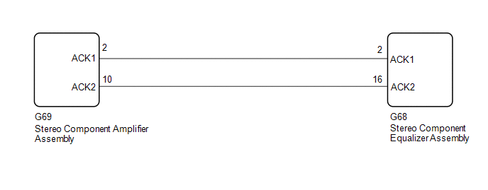
CHECK HARNESS AND CONNECTOR (STEREO COMPONENT EQUALIZER ASSEMBLY - STEREO COMPONENT AMPLIFIER ASSEMBLY) |
(a) Disconnect the G68 stereo component equalizer assembly connector.
(b) Disconnect the G69 stereo component amplifier assembly connector.
(c) Measure the resistance according to the value(s) in the table below.
Standard Resistance:
|
Tester Connection | Condition |
Specified Condition |
|
G68-2 (ACK1) - G69-2 (ACK1) |
Always | Below 1 Ω |
|
G68-16 (ACK2) - G69-10 (ACK2) |
Always | Below 1 Ω |
|
G68-2 (ACK1) or G69-2 (ACK1) - Body ground |
Always | 10 kΩ or higher |
|
G68-16 (ACK2) or G69-10 (ACK2) - Body ground |
Always | 10 kΩ or higher |
| NG |
| REPAIR OR REPLACE HARNESS OR CONNECTOR |
|
OK | |
| |
| 4. |
REPLACE STEREO COMPONENT EQUALIZER ASSEMBLY |
(a) Replace the stereo component amplifier assembly with a new or known good one.
Click here 
|
NEXT | |
| |
(a) Clear the DTCs.
Body Electrical > Active Noise Control > Clear DTCs
|
NEXT | |
| |
(a) Check for DTCs.
Body Electrical > Active Noise Control > Trouble Codes
OK:
DTC B1AA187 is not output.
| OK |
| END (STEREO COMPONENT AMPLIFIER ASSEMBLY IS DEFECTIVE) |
| NG |
| REPLACE STEREO COMPONENT EQUALIZER ASSEMBLY |
Front Left Microphone Circuit Component Internal Failure (B1AA296,B1AA31C)
DESCRIPTION
These DTCs are stored when a malfunction occurs in the No. 1 active noise control microphone system.
|
DTC No. | Detection Item |
DTC Detection Condition | Trouble Area |
|
B1AA296 | Front Left Microphone Circuit Component Internal Failure |
Stereo
component equalizer assembly detects malfunction in No. 1 active noise
control microphone for 4 seconds or more continuously when engine speed
is 1200 rpm or more* |
- Harness or connector
- No. 1 active noise control microphone
- Stereo component equalizer assembly
|
| B1AA31C |
Front Left Microphone Circuit Circuit Voltage Out of Range |
Stereo
component equalizer assembly detects No. 1 active noise control
microphone connection malfunction for 4 seconds or more continuously* |
- Harness or connector
- No. 1 active noise control microphone
- Stereo component equalizer assembly
|
HINT:
*: Malfunction monitoring is not performed under the following conditions, in order to prevent erroneous detection.
- After engine switch is turned on (ACC) for 3 seconds or more.
- After the battery voltage returns to normal for 3 seconds.
- Before 3 seconds have elapsed after battery voltage has returned to normal.
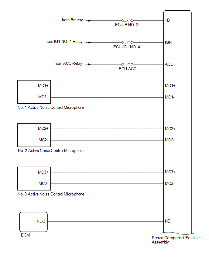
WIRING DIAGRAM
PROCEDURE
(a) Clear the DTCs.
Body Electrical > Active Noise Control > Clear DTCs
|
NEXT |
 | |
(a) Check for DTCs.
Body Electrical > Active Noise Control > Trouble Codes
OK:
DTC B1AA296 and B1AA31C are not output.
| OK |
 | USE SIMULATION METHOD TO CHECK |
|
NG | |
| |
| 3. |
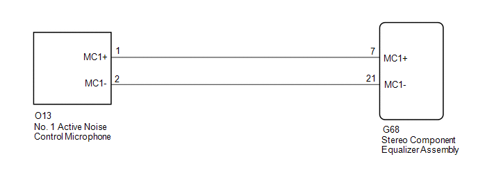
CHECK HARNESS AND CONNECTOR (STEREO COMPONENT EQUALIZER ASSEMBLY - NO. 1 ACTIVE NOISE CONTROL MICROPHONE) |
(a) Disconnect the G68 stereo component equalizer assembly connector.
(b) Disconnect the O13 No. 1 active noise control microphone connector.
(c) Measure the resistance according to the value(s) in the table below.
Standard Resistance:
|
Tester Connection | Condition |
Specified Condition |
|
G68-7 (MC1+) - O13-1 (MC1+) |
Always | Below 1 Ω |
|
G68-21 (MC1-) - O13-2 (MC1-) |
Always | Below 1 Ω |
|
G68-7 (MC1+) or O13-1 (MC1+) - Body ground |
Always | 10 kΩ or higher |
|
G68-21 (MC1-) or O13-2 (MC1-) - Body ground |
Always | 10 kΩ or higher |
| NG |
| REPAIR OR REPLACE HARNESS OR CONNECTOR |
|
OK | |
| |
| 4. |
REPLACE NO. 1 ACTIVE NOISE CONTROL MICROPHONE |
(a) Replace the No. 1 active noise control microphone with a new or known good one.
Click here 
|
NEXT | |
| |
(a) Clear the DTCs.
Body Electrical > Active Noise Control > Clear DTCs
|
NEXT | |
| |
(a) Check for DTCs.
Body Electrical > Active Noise Control > Trouble Codes
OK:
DTC B1AA296 and B1AA31C are not output.
| OK |
| END (NO. 1 ACTIVE NOISE CONTROL MICROPHONE IS DEFECTIVE) |
| NG |
| REPLACE STEREO COMPONENT EQUALIZER ASSEMBLY |
Front Right Microphone Circuit Component Internal Failure (B1AA696,B1AA71C)
DESCRIPTION
These DTCs are stored when a malfunction occurs in the No. 2 active noise control microphone system.
|
DTC No. | Detection Item |
DTC Detection Condition | Trouble Area |
|
B1AA696 | Front Right Microphone Circuit Component Internal Failure |
Stereo
component equalizer assembly detects malfunction in No. 2 active noise
control microphone for 4 seconds or more continuously when engine speed
is 1200 rpm or more* |
- Harness or connector
- No. 2 active noise control microphone
- Stereo component equalizer assembly
|
| B1AA71C |
Front Right Microphone Circuit Circuit Voltage Out of Range |
Stereo
component equalizer assembly detects No. 2 active noise control
microphone connection malfunction for 4 seconds or more continuously* |
- Harness or connector
- No. 2 active noise control microphone
- Stereo component equalizer assembly
|
HINT:
*: Malfunction monitoring is not performed under the following conditions, in order to prevent erroneous detection.
- After engine switch is turned on (ACC) for 3 seconds or more.
- After the battery voltage returns to normal for 3 seconds.
- Before 3 seconds have elapsed after battery voltage has returned to normal.
WIRING DIAGRAM
PROCEDURE
(a) Clear the DTCs.
Body Electrical > Active Noise Control > Clear DTCs
|
NEXT |
 | |
(a) Check for DTCs.
Body Electrical > Active Noise Control > Trouble Codes
OK:
DTC B1AA696 and B1AA71C are not output.
| OK |
 | USE SIMULATION METHOD TO CHECK |
|
NG | |
| |
| 3. |
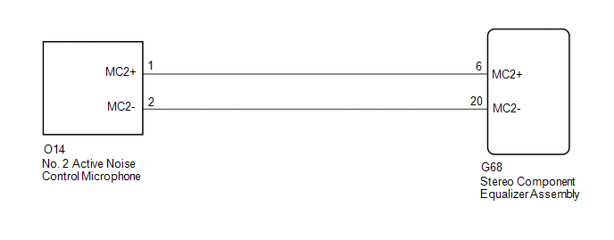
CHECK HARNESS AND CONNECTOR (STEREO COMPONENT EQUALIZER ASSEMBLY - NO. 2 ACTIVE NOISE CONTROL MICROPHONE) |
(a) Disconnect the G68 stereo component equalizer assembly connector.
(b) Disconnect the O14 No. 2 active noise control microphone connector.
(c) Measure the resistance according to the value(s) in the table below.
Standard Resistance:
|
Tester Connection | Condition |
Specified Condition |
|
G68-6 (MC2+) - O14-1 (MC2+) |
Always | Below 1 Ω |
|
G68-20 (MC2-) - O14-2 (MC2-) |
Always | Below 1 Ω |
|
G68-6 (MC2+) or O14-1 (MC2+) - Body ground |
Always | 10 kΩ or higher |
|
G68-20 (MC2-) or O14-2 (MC2-) - Body ground |
Always | 10 kΩ or higher |
| NG |
| REPAIR OR REPLACE HARNESS OR CONNECTOR |
|
OK | |
| |
| 4. |
REPLACE NO. 2 ACTIVE NOISE CONTROL MICROPHONE |
(a) Replace the No. 2 active noise control microphone with a new or known good one.
Click here 
|
NEXT | |
| |
(a) Clear the DTCs.
Body Electrical > Active Noise Control > Clear DTCs
|
NEXT | |
| |
(a) Check for DTCs.
Body Electrical > Active Noise Control > Trouble Codes
OK:
DTC B1AA696 and B1AA71C are not output.
| OK |
| END (NO. 2 ACTIVE NOISE CONTROL MICROPHONE IS DEFECTIVE) |
| NG |
| REPLACE STEREO COMPONENT EQUALIZER ASSEMBLY |
Rear Center Microphone Circuit Component Internal Failure (B1AAA96,B1AAB1C)
DESCRIPTION
These DTCs are stored when a malfunction occurs in the No. 3 active noise control microphone system.
|
DTC No. | Detection Item |
DTC Detection Condition | Trouble Area |
|
B1AAA96 | Rear Center Microphone Circuit Component Internal Failure |
Stereo
component equalizer assembly detects malfunction in No. 3 active noise
control microphone for 4 seconds or more continuously when engine speed
is 1200 rpm or more* |
- Harness or connector
- No. 3 active noise control microphone
- Stereo component equalizer assembly
|
| B1AAB1C |
Rear Center Microphone Circuit Circuit Voltage Out of Range |
Stereo
component equalizer assembly detects No. 3 active noise control
microphone connection malfunction for 4 seconds or more continuously* |
- Harness or connector
- No. 3 active noise control microphone
- Stereo component equalizer assembly
|
HINT:
*: Malfunction monitoring is not performed under the following conditions, in order to prevent erroneous detection.
- After engine switch is turned on (ACC) for 3 seconds or more.
- After the battery voltage returns to normal for 3 seconds.
- Before 3 seconds have elapsed after battery voltage has returned to normal.
WIRING DIAGRAM
PROCEDURE
(a) Clear the DTCs.
Body Electrical > Active Noise Control > Clear DTCs
|
NEXT |
 | |
(a) Check for DTCs.
Body Electrical > Active Noise Control > Trouble Codes
OK:
DTC B1AAA96 and B1AAB1C are not output.
| OK |
 | USE SIMULATION METHOD TO CHECK |
|
NG | |
| |
| 3. |
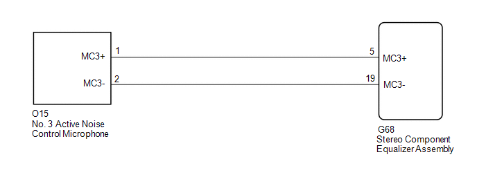
CHECK HARNESS AND CONNECTOR (STEREO COMPONENT EQUALIZER ASSEMBLY - NO. 3 ACTIVE NOISE CONTROL MICROPHONE) |
(a) Disconnect the G68 stereo component equalizer assembly connector.
(b) Disconnect the O15 No. 3 active noise control microphone connector.
(c) Measure the resistance according to the value(s) in the table below.
Standard Resistance:
|
Tester Connection | Condition |
Specified Condition |
|
G68-5 (MC3+) - O15-1 (MC3+) |
Always | Below 1 Ω |
|
G68-19 (MC3-) - O15-2 (MC3-) |
Always | Below 1 Ω |
|
G68-5 (MC3+) or O15-1 (MC3+) - Body ground |
Always | 10 kΩ or higher |
|
G68-19 (MC3-) or O15-2 (MC3-) - Body ground |
Always | 10 kΩ or higher |
| NG |
| REPAIR OR REPLACE HARNESS OR CONNECTOR |
|
OK | |
| |
| 4. |
REPLACE NO. 3 ACTIVE NOISE CONTROL MICROPHONE |
(a) Replace the No. 3 active noise control microphone with a new or known good one.
Click here 
|
NEXT | |
| |
(a) Clear the DTCs.
Body Electrical > Active Noise Control > Clear DTCs
|
NEXT | |
| |
(a) Check for DTCs.
Body Electrical > Active Noise Control > Trouble Codes
OK:
DTC B1AAA96 and B1AAB1C are not output.
| OK |
| END (NO. 3 ACTIVE NOISE CONTROL MICROPHONE IS DEFECTIVE) |
| NG |
| REPLACE STEREO COMPONENT EQUALIZER ASSEMBLY |
Data List / Active Test
DATA LIST / ACTIVE TEST
DATA LIST
NOTICE:
In
the following table, the values listed under "Normal Condition" are
reference values. Do not depend solely on these reference values when
deciding whether a part is faulty or not.
HINT:
Using
the Techstream to read the Data List allows the values or states of
switches, sensors, actuators and other items to be read without removing
any parts. This non-intrusive inspection can be very useful because
intermittent conditions or signals may be discovered before parts or
wiring is disturbed. Reading the Data List information early in
troubleshooting is one way to save diagnostic time.
(a) Connect the Techstream to the DLC3.
(b) Turn the engine switch on (IG).
(c) Turn the Techstream on.
(d) Enter the following menus: Body Electrical / Active Noise Control / Data List.
(e) Read the Data List according to the display on the Techstream.
Body Electrical > Active Noise Control > Data List
|
Tester Display | Measurement Item |
Range | Reference Value |
Diagnostic Note |
|
Total Distance Traveled |
Displays the current total driving distance |
0 to 16777215 | Equivalent to the actual total driving distance |
Refer to the Total Distance Traveled - Unit for the units |
|
Total Distance Traveled - Unit |
Displays the current total driving distance units |
km or mile | Units according destination |
- |
ACTIVE TEST
HINT:
Using
the Techstream to perform Active Tests allows relays, VSVs, actuators
and other items to be operated without removing any parts. This
non-intrusive functional inspection can be very useful because
intermittent operation may be discovered before parts or wiring is
disturbed. Performing Active Tests early in troubleshooting is one way
to save diagnostic time. Data List information can be displayed while
performing Active Tests.
(a) Connect the Techstream to the DLC3.
(b) Turn the engine switch on (IG).
(c) Turn the Techstream on.
(d) Enter the following menus: Body Electrical / Active Noise Control / Active Test.
(e) Perform the Active Test according to the display on the Techstream.
Body Electrical > Active Noise Control > Active Test
|
Tester Display | Measurement Item |
Control Range | Diagnostic Note |
|
Sound (All CH) | Test
sound outputs in following order: Front No. 1 speaker assembly LH →
Front No. 1 speaker assembly RH → Rear No. 3 speaker assembly |
ON or OFF | - |
|
Sound "CH1" | Test sound output from front No. 1 speaker assembly LH |
ON or OFF | - |
|
Sound "CH2" | Test sound output from front No. 1 speaker assembly RH |
ON or OFF | - |
|
Sound "CH3" | Test sound output from rear No. 3 speaker assembly |
ON or OFF | - |
|
Sound "CH4" | - |
- | Cannot be used |
Diagnostic Trouble Code Chart
DIAGNOSTIC TROUBLE CODE CHART
Active Noise Control System |
DTC No. | Detection Item |
Link |
| B1AA044 |
ANC ECU EEPROM Data Memory Failure |
 |
|
B1AA187 | UART Communication Between ANC and Audio Amplifier Missing Message |
|
|
B1AA296 | Front Left Microphone Circuit Component Internal Failure |
|
|
B1AA31C | Front Left Microphone Circuit Circuit Voltage Out of Range |
|
|
B1AA696 | Front Right Microphone Circuit Component Internal Failure |
|
|
B1AA71C | Front Right Microphone Circuit Circuit Voltage Out of Range |
|
|
B1AAA96 | Rear Center Microphone Circuit Component Internal Failure |
|
|
B1AAB1C | Rear Center Microphone Circuit Circuit Voltage Out of Range |
|
|
P033531 | Crankshaft Position Sensor "A" No Signal |
|
|
U010087 | Lost Communication With ECM/PCM "A" Missing Message |
|
|
U012987 | Lost Communication With Brake System Control Module Missing Message |
|
|
U014087 | Lost Communication with Body Control Module Missing Message |
|
Dtc Check / Clear
DTC CHECK / CLEAR
CHECK FOR DTC (CHECK USING TECHSTREAM)
(a) Connect the Techstream to the DLC3.
(b) Turn the engine switch on (IG).
(c) Turn the Techstream on.
(d) Enter the following menus: Body Electrical / Active Noise Control / Trouble Codes.
Body Electrical > Active Noise Control > Trouble Codes
(e) Check the details of the DTC(s).
Click here

CLEAR DTC (CLEAR USING TECHSTREAM)
(a) Connect the Techstream to the DLC3.
(b) Turn the engine switch on (IG).
(c) Turn the Techstream on.
(d) Enter the following menus: Body Electrical / Active Noise Control / Trouble Codes.
(e) Clear DTCs.
Click here
Body Electrical > Active Noise Control > Clear DTCsFreeze Frame Data
FREEZE FRAME DATA
CHECK FREEZE FRAME DATA
HINT:
Whenever
an active noise control system DTC is stored, the stereo component
equalizer assembly stores the current vehicle state as freeze frame
data.
(a) Connect the Techstream to the DLC3.
(b) Turn the engine switch on (IG).
(c) Turn the Techstream on.
(d) Enter the following menus: Body Electrical / Active Noise Control / Trouble Codes.
Body Electrical > Active Noise Control > Trouble Codes
(e) According to the Techstream display, select a DTC that stored freeze frame data.
NOTICE:
Read the freeze frame data recorded when the DTC was stored.
LIST OF FREEZE FRAME DATA
Body Electrical > Active Noise Control
|
Tester Display | Measurement Item |
Range | Reference Value |
Diagnostic Note |
|
Total Distance Traveled |
Displays the current total driving distance |
0 to 16777215 | Equivalent to the actual total driving distance |
Refer to the Total Distance Traveled - Unit for the units |
|
Total Distance Traveled - Unit |
Displays the current total driving distance units |
km or mile | Units according destination |
- |
How To Proceed With Troubleshooting
PROCEDURE
|
1. | VEHICLE BROUGHT TO WORKSHOP |
|
NEXT |
 | |
| 2. |
CUSTOMER PROBLEM ANALYSIS AND SYMPTOM CHECK |
|
NEXT | |
| |
| 3. |
INSPECT BATTERY VOLTAGE |
(a) Measure the battery voltage.
Standard voltage:
11 to 14 V
HINT:
If the battery voltage is below 11 V, recharge or replace the battery before proceeding to the next step.
|
NEXT | |
| |
| 4. |
CHECK CAN COMMUNICATION SYSTEM |
(a) Check if the CAN communication system is functioning normally.
Click here 
|
Result | Proceed to |
|
CAN communication system DTCs are not output. |
A |
| CAN communication system DTCs are output. |
B |
| B |
 | GO TO CAN COMMUNICATION SYSTEM |
|
A | |
| |
(a) Check for DTCs and note any codes that are output.
Body Electrical > Active Noise Control > Trouble Codes
(b) Clear the DTCs.
Body Electrical > Active Noise Control > Clear DTCs
(c) Recheck for DTCs. Try to reproduce the active noise control system DTCs by duplicating the conditions indicated by the DTCs.
Body Electrical > Active Noise Control > Trouble Codes
|
Result | Proceed to |
|
DTCs are not output (Problem symptom occurs) |
A |
| DTCs are output |
B |
| DTCs are not output (Problem symptom does not occur) |
C |
| B |
| GO TO DIAGNOSTIC TROUBLE CODE CHART |
| C |
| USE SIMULATION METHOD TO CHECK |
|
A | |
| |
| 6. |
PROBLEM SYMPTOMS TABLE |
HINT:
Refer to Problem Symptoms Table.
Click here
|
Result | Proceed to |
|
Fault is not listed in Problem Symptoms Table. |
A |
| Fault is listed in Problem Symptoms Table. |
B |
| B |
| PERFORM TROUBLESHOOTING BASED ON PROBLEM SYMPTOM |
|
A | |
| |
| 7. |
OVERALL ANALYSIS AND TROUBLESHOOTING |
(a) Terminals of ECU
Click here
(b) Data List / Active Test
Click here
|
NEXT | |
| |
| 8. |
ADJUST, REPAIR OR REPLACE |
|
NEXT | |
| |
| NEXT |
| END |
Input / Output Signal Circuit
DESCRIPTION
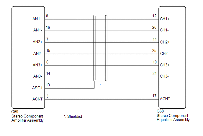
The stereo component equalizer assembly uses this circuit to send and receive signals to and from the stereo component assembly.
WIRING DIAGRAM
PROCEDURE
| 1. |
CHECK HARNESS AND CONNECTOR (STEREO COMPONENT EQUALIZER ASSEMBLY - STEREO COMPONENT AMPLIFIER ASSEMBLY) |
(a) Disconnect the G68 stereo component equalizer assembly connector.
(b) Disconnect the G69 stereo component amplifier assembly connector.
(c) Measure the resistance according to the value(s) in the table below.
Standard Resistance:
|
Tester Connection | Condition |
Specified Condition |
|
G68-12 (CH1+) - G69-8 (AN1+) |
Always | Below 1 Ω |
|
G68-26 (CH1-) - G69-16 (AN1-) |
Always | Below 1 Ω |
|
G68-11 (CH2+) - G69-7 (AN2+) |
Always | Below 1 Ω |
|
G68-25 (CH2-) - G69-15 (AN2-) |
Always | Below 1 Ω |
|
G68-10 (CH3+) - G69-6 (AN3+) |
Always | Below 1 Ω |
|
G68-24 (CH3-) - G69-14 (AN3-) |
Always | Below 1 Ω |
|
G69-13 (ASG1) - Body ground |
Always | 10 kΩ or higher |
|
G68-17 (ACNT) - G69-3 (ACNT) |
Always | Below 1 Ω |
|
G68-12 (CH1+) or G69-8 (AN1+) - Body ground |
Always | 10 kΩ or higher |
|
G68-26 (CH1-) or G69-16 (AN1-) - Body ground |
Always | 10 kΩ or higher |
|
G68-11 (CH2+) or G69-7 (AN2+) - Body ground |
Always | 10 kΩ or higher |
|
G68-25 (CH2-) or G69-15 (AN2-) - Body ground |
Always | 10 kΩ or higher |
|
G68-10 (CH3+) or G69-6 (AN3+) - Body ground |
Always | 10 kΩ or higher |
|
G68-24 (CH3-) or G69-14 (AN3-) - Body ground |
Always | 10 kΩ or higher |
|
G68-17 (ACNT) or G69-3 (ACNT) - Body ground |
Always | 10 kΩ or higher |
| OK |
 | PROCEED TO NEXT SUSPECTED AREA SHOWN IN PROBLEM SYMPTOMS TABLE |
| NG |
| REPAIR OR REPLACE HARNESS OR CONNECTOR |
Crankshaft Position Sensor "A" No Signal (P033531)
DESCRIPTION
This DTC is output when a malfunction has occurred in the engine pulse signal system from the ECM.
|
DTC No. | Detection Item |
DTC Detection Condition | Trouble Area |
|
P033531 | Crankshaft Position Sensor "A" No Signal |
Stereo
component equalizer assembly detects malfunction in engine pulse signal
system for 10 seconds or more continuously when engine speed is between
500 and 6000 rpm* |
- Harness or connector
- SFI system
- Stereo component equalizer assembly
|
HINT:
*: Malfunction monitoring is not performed under the following conditions, in order to prevent erroneous detection.
- After engine switch is turned on (ACC) for 3 seconds or more.
- After the battery voltage returns to normal for 3 seconds.
- Before 3 seconds have elapsed after battery voltage has returned to normal.
WIRING DIAGRAM
CAUTION / NOTICE / HINT
NOTICE:
Refer to  when replacing the ECM.
PROCEDURE
(a) Clear the DTCs.
Body Electrical > Active Noise Control > Clear DTCs
|
NEXT |
 | |
(a) Check for DTCs.
Body Electrical > Active Noise Control > Trouble Codes
OK:
DTC P033531 is not output.
| OK |
 | USE SIMULATION METHOD TO CHECK |
|
NG | |
| |
| 3. |
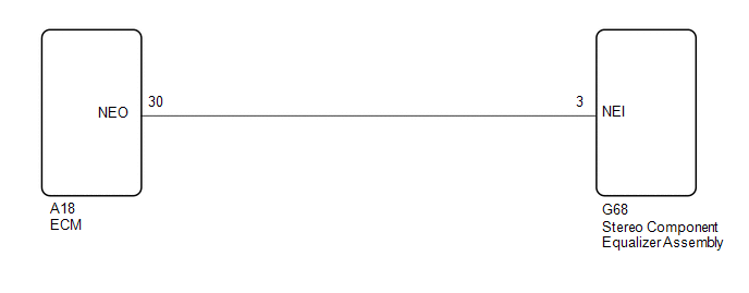
CHECK HARNESS AND CONNECTOR (STEREO COMPONENT EQUALIZER ASSEMBLY - ECM) |
(a) Disconnect the G68 stereo component equalizer assembly connector.
(b) Disconnect the A18 ECM connector.
(c) Measure the resistance according to the value(s) in the table below.
Standard Resistance:
|
Tester Connection | Condition |
Specified Condition |
|
G68-3 (NEI) - A18-30 (NEO) |
Always | Below 1 Ω |
|
G68-3 (NEI) or A18-30 (NEO) - Body ground |
Always | 10 kΩ or higher |
| NG |
| REPAIR OR REPLACE HARNESS OR CONNECTOR |
|
OK | |
| |
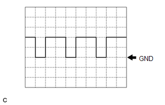
(a)
According to the table and using an oscilloscope, measure the waveform
with the stereo component equalizer assembly connected.
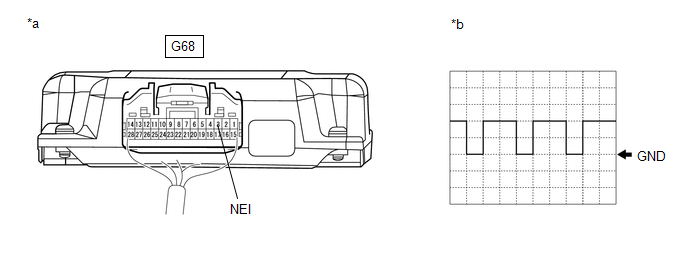
|
*a | Component with harness connected
(Stereo Component Equalizer Assembly) |
*b | Waveform |
|
Item | Condition |
|
Measurement terminal |
G68-3 (NEI) - Body ground |
|
Tool setting | 5 V/DIV., 20 ms./DIV. |
|
Vehicle condition | Idling after warming up |
OK:
The waveform is similar to that shown in the illustration.
HINT:
The
oscilloscope waveform shown in the illustration is an example for
reference only. The waveform fluctuates according to engine speed.
| OK |
| REPLACE STEREO COMPONENT EQUALIZER ASSEMBLY |
| NG |
| GO TO SFI SYSTEM |
Parts Location
PARTS LOCATION
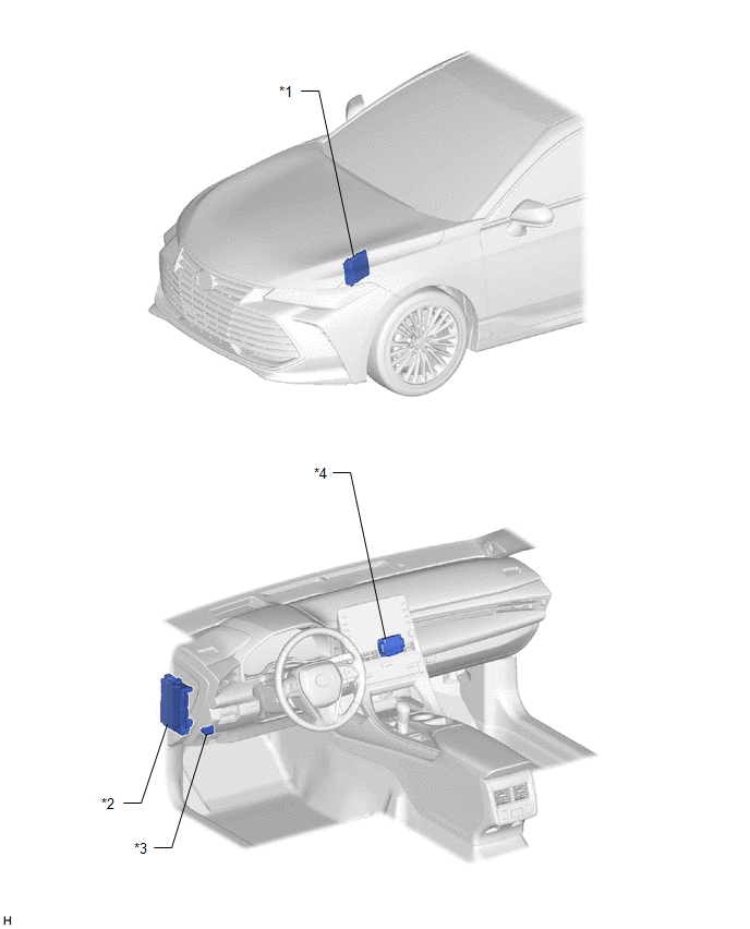
ILLUSTRATION
|
*1 | ECM |
*2 | INSTRUMENT PANEL JUNCTION BLOCK ASSEMBLY
- ECU-B NO. 2 FUSE - ECU-IG1 NO. 4 FUSE - ECU-ACC FUSE |
|
*3 | DLC3 |
*4 | STEREO COMPONENT EQUALIZER ASSEMBLY |
ILLUSTRATION
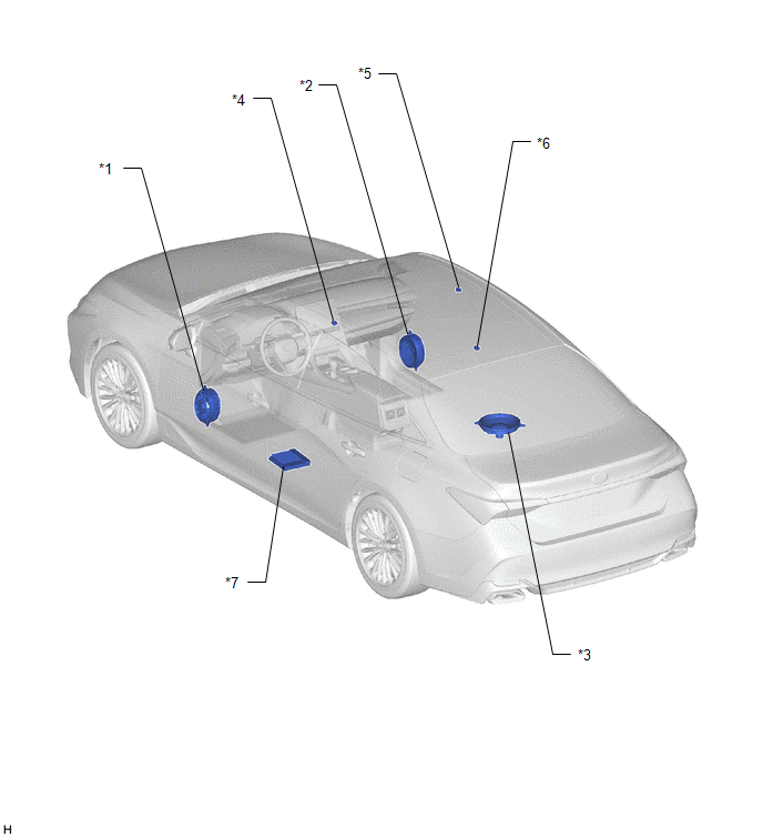
|
*1 | FRONT NO. 1 SPEAKER ASSEMBLY LH |
*2 | FRONT NO. 1 SPEAKER ASSEMBLY RH |
|
*3 | REAR NO. 3 SPEAKER ASSEMBLY |
*4 | NO. 1 ACTIVE NOISE CONTROL MICROPHONE |
|
*5 | NO. 2 ACTIVE NOISE CONTROL MICROPHONE |
*6 | NO. 3 ACTIVE NOISE CONTROL MICROPHONE |
|
*7 | STEREO COMPONENT AMPLIFIER ASSEMBLY |
- | - |
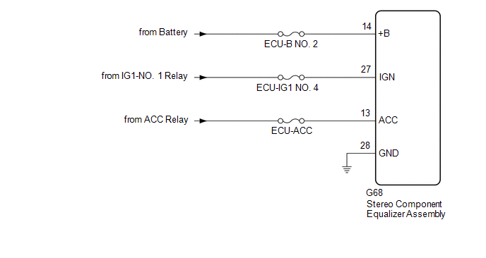
Power Source Circuit
DESCRIPTION
This circuit is the power source circuit for the stereo component equalizer assembly.
WIRING DIAGRAM
CAUTION / NOTICE / HINT
NOTICE:
Inspect the fuses and relays for circuits related to this system before performing the following procedure.
PROCEDURE
| 1. |
CHECK HARNESS AND CONNECTOR (STEREO COMPONENT EQUALIZER ASSEMBLY - BATTERY [+B, IGN] AND BODY GROUND) |
| (a) Disconnect the stereo component equalizer assembly connector. |
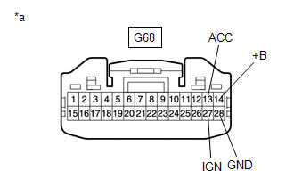 |
|
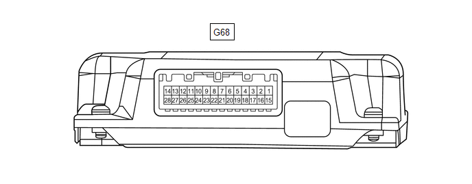
*a | Front view of wire harness connector
(to Stereo Component Equalizer Assembly) | | |
(b) Measure the voltage according to the value(s) in the table below.
Standard Voltage:
|
Tester Connection | Condition |
Specified Condition |
|
G68-14 (+B) - Body ground |
Always | 11 to 14 V |
|
G68-27 (IGN) - Body ground |
Engine switch on (IG) |
11 to 14 V |
|
G68-13 (ACC) - Body ground |
Engine switch on (ACC) |
11 to 14 V |
(c) Measure the resistance according to the value(s) in the table below.
Standard Resistance:
|
Tester Connection | Condition |
Specified Condition |
|
G68-28 (GND) - Body ground |
Always | Below 1 Ω |
| OK |
 | PROCEED TO NEXT SUSPECTED AREA SHOWN IN PROBLEM SYMPTOMS TABLE |
| NG |
| REPAIR OR REPLACE HARNESS OR CONNECTOR |
Precaution
PRECAUTION
PRECAUTION FOR ACTIVE NOISE CONTROL SYSTEM
(a) If the active noise control microphone garnish hole is blocked, clean away the blockage and perform diagnosis.
(b) If heavy objects are loaded onto the rear package tray, remove them before performing diagnosis.
Problem Symptoms Table
PROBLEM SYMPTOMS TABLE
NOTICE:
- Before checking parts for malfunctions, check that the audio system operates normally.
- Use the table below to help determine the cause of problem symptoms. If
multiple suspected areas are listed, the potential causes of the
symptoms are listed in order of probability in the "Suspected Area"
column of the table. Check each symptom by checking the suspected areas
in the order they are listed. Replace parts as necessary.
- Inspect the fuses and relays related to this system before inspecting the suspected areas below.
HINT:
Removing
dealer installed options and optional components before performing
diagnosis makes it easier to determine the location of a malfunction.
Active Noise Control System |
Symptom | Suspected Area |
Link |
|
Muffled engine sounds in cabin |
Proceed to "Power Source Circuit" |
 |
|
Proceed to "Input / Output Signal Circuit" |
|
|
Front No. 1 speaker assembly LH |
|
|
Front No. 1 speaker assembly RH |
|
|
Rear No. 3 speaker assembly |
|
|
Harness or connector |
- |
| Stereo component equalizer assembly |
|
|
Stereo component amplifier assembly |
|
|
Abnormal noise from speakers |
Front No. 1 speaker assembly LH |
|
|
Front No. 1 speaker assembly RH |
|
|
Rear No. 3 speaker assembly |
|
|
Harness or connector |
- |
| Stereo component equalizer assembly |
|
|
Stereo component amplifier assembly |
|
System Description
SYSTEM DESCRIPTION
ACTIVE NOISE CONTROL SYSTEM
(a)
The active noise control system is a system that detects muffled engine
sounds produced in sync that fluctuates according to the engine speed,
by using the active noise control microphone and outputs anti-phase
control sound through the audio speakers to reduce muffled engine
sounds.
The active noise control system includes the following functions.
|
Function Name | Function Description |
Operation Conditions |
|
ANC (Active Noise Control) Function |
Function that reduces noise by using anti-phase and vibration control sound to interfere with muffled sounds |
Engine running, engine speed 1000 rpm or higher |
|
ESE (Engine Sound Enhancement) Function |
Function
that produces realistic engine sounds by adding frequency component
sound according to driving conditions such as vehicle speed and
accelerator pedal depression | Engine running, vehicle speed exceeding 0 km/h (0 mph) |
System Diagram
SYSTEM DIAGRAM
Terminals Of Ecu
TERMINALS OF ECU
STEREO COMPONENT EQUALIZER ASSEMBLY
|
Terminal No. (Symbol) | Wiring Color |
Terminal Description | Condition |
Specified Condition |
|
G68-1 (CANH) | P |
CAN communication signal |
- | - |
|
G68-2 (ACK1) | V |
Serial communication (UART) signal |
- | - |
|
G68-3 (NEI) - G68-28 (GND) |
LA-B - W-B | Engine pulse signal |
Idling with warm engine |
Pulse generation (See waveform 1) |
|
G68-5 (MC3+) - G68-28 (GND) |
R - W-B | Active noise control microphone input signal |
No. 3 active noise control microphone tapped with finger |
Pulse generation |
|
G68-6 (MC2+) - G68-28 (GND) |
B - W-B | Active noise control microphone input signal |
No. 2 active noise control microphone tapped with finger |
Pulse generation |
|
G68-7 (MC1+) - G68-28 (GND) |
V - W-B | Active noise control microphone input signal |
No. 1 active noise control microphone tapped with finger |
Pulse generation |
|
G68-10 (CH3+) - G68-28 (GND) |
SB - W-B | Active noise control microphone output signal |
Active noise control system operating |
Pulse generation |
|
G68-11 (CH2+) - G68-28 (GND) |
L - W-B | Active noise control microphone output signal |
Active noise control system operating |
Pulse generation |
|
G68-12 (CH1+) - G68-28 (GND) |
Y - W-B | Active noise control microphone output signal |
Active noise control system operating |
Pulse generation |
|
G68-13 (ACC) - G68-28 (GND) |
P - W-B | Power source (ACC) |
Engine switch on (ACC) |
11 to 14 V |
|
G68-14 (+B) - G68-28 (GND) |
LA-G - W-B | Power source |
Always | 11 to 14 V |
|
G68-15 (CANL) | W |
CAN communication signal |
- | - |
|
G68-16 (ACK2) | BE |
Serial communication (UART) signal |
- | - |
|
G68-17 (ACNT) - G68-28 (GND) |
SB - W-B |
Active noise control system control signal |
Engine switch on (IG) |
Below 1 V |
|
Engine switch on (ACC) |
4.5 V or higher |
|
G68-19 (MC3-) - G68-28 (GND) |
G - W-B | Active noise control microphone input signal |
Always | Below 1 Ω |
|
G68-20 (MC2-) - G68-28 (GND) |
P - W-B | Active noise control microphone input signal |
Always | Below 1 Ω |
|
G68-21 (MC1-) - G68-28 (GND) |
LG - W-B | Active noise control microphone input signal |
Always | Below 1 Ω |
|
G68-24 (CH3-) - G68-28 (GND) |
P - W-B | Active noise control microphone output signal |
Active noise control system operating |
Pulse generation |
|
G68-25 (CH2-) - G68-28 (GND) |
V - W-B | Active noise control microphone output signal |
Active noise control system operating |
Pulse generation |
|
G68-26 (CH1-) - G68-28 (GND) |
LG - W-B | Active noise control microphone output signal |
Active noise control system operating |
Pulse generation |
|
G68-27 (IGN) - G68-28 (GND) |
LA-SB - W-B | Power source (IG) |
Engine switch on (IG) |
11 to 14 V |
|
G68-28 (GND) - Body ground |
W-B - Body ground | Ground |
Always | Below 1 Ω |
(a) Waveform 1
HINT:
The
oscilloscope waveform shown in the illustration is an example for
reference only. The waveform fluctuates according to engine speed.
|
Item | Condition |
|
Measurement terminal |
G68-3 (NEI) - G68-28 (GND) |
|
Tool setting | 5 V/DIV., 20 ms./DIV. |
|
Vehicle condition | Idling after warming up |
STEREO COMPONENT AMPLIFIER ASSEMBLY

|
Terminal No. (Symbol) | Wiring Color |
Terminal Description | Condition |
Specified Condition |
|
G69-2 (ACK1) | GR |
Serial communication (UART) signal |
- | - |
|
G69-3 (ACNT) |
B | Active noise control system control signal |
Active noise control system operating |
Below 1 V |
|
Active noise control system not operating |
4.5 V or higher |
|
G69-6 (AN3+) | G |
Active noise control microphone input signal |
Active noise control system operating |
Pulse generation |
|
G69-7 (AN2+) | R |
Active noise control microphone input signal |
Active noise control system operating |
Pulse generation |
|
G69-8 (AN1+) | W |
Active noise control microphone input signal |
Active noise control system operating |
Pulse generation |
|
G69-10 (ACK2) | V |
Serial communication (UART) signal |
- | - |
|
G69-13 (ASG1) | Shielded - W-B |
Shield ground | Always |
Below 1 Ω |
|
G69-14 (AN3-) | GR |
Active noise control microphone input signal |
Active noise control system operating |
Pulse generation |
|
G69-15 (AN2-) | L |
Active noise control microphone input signal |
Active noise control system operating |
Pulse generation |
|
G69-16 (AN1-) | B |
Active noise control microphone input signal |
Active noise control system operating |
Pulse generation |
Lost Communication With ECM/PCM "A" Missing Message (U010087,U012987,U014087)
DESCRIPTION
These DTCs are stored when a malfunction occurs in the CAN communication circuit.
|
DTC No. | Detection Item |
DTC Detection Condition | Trouble Area |
|
U010087 | Lost Communication With ECM/PCM "A" Missing Message |
Stereo
component equalizer assembly detects CAN communication malfunction in
engine system for 1 second or more continuously, 3 seconds or more after
engine switch is turned on (IG)* |
CAN communication system |
|
U012987 | Lost Communication With Brake System Control Module Missing Message |
Stereo
component equalizer assembly detects CAN communication malfunction in
brake system for 1 second or more continuously, 3 seconds or more after
engine switch is turned on (IG)* | CAN communication system |
|
U014087 | Lost Communication with Body Control Module Missing Message |
Stereo
component equalizer assembly detects CAN communication malfunction in
main body ECU for 3 seconds or more continuously, 3 seconds or more
after engine switch is turned on (IG)* |
CAN communication system |
HINT:
*: Malfunction monitoring is not performed under the following conditions, in order to prevent erroneous detection.
- After engine switch is turned on (ACC) for 3 seconds or more.
- After the battery voltage returns to normal for 3 seconds.
- Before 3 seconds have elapsed after battery voltage has returned to normal.
PROCEDURE
(a) Clear the DTCs.
Body Electrical > Active Noise Control > Clear DTCs
|
NEXT |
 | |
(a) Check for DTCs.
Body Electrical > Active Noise Control > Trouble Codes
OK:
DTC U010087, U012987 and U014087 are not output
HINT:
- If CAN communication system malfunction DTCs are output, they may also be output for other systems.
- If the CAN communication system has been checked and repaired in other
systems, the DTC will not be output after rechecking for DTCs.
- If the DTC is output frequently, duplicate the conditions that cause a
malfunction and perform the check again, even though the DTC was not
output after rechecking for DTCs.
Click here 
| OK |
 | USE SIMULATION METHOD TO CHECK |
| NG |
| GO TO CAN COMMUNICATION SYSTEM |


