"CHK" message(s) are displayed on the SIGNAL CHECK screen.
DESCRIPTION
On the SIGNAL CHECK screen, it is possible to check if the signals sent to the parking assist ECU are normal.
Click here 
HINT:
- On the SIGNAL CHECK screen, "OK" (blue) is displayed for items with a normal inspection result or input state.
- On the SIGNAL CHECK screen, "CHK" (red) is displayed for items with an abnormal inspection result or input state.
- Displayed items may differ depending on vehicle specifications.
|
Item | Signal Input Method |
Detail | DTC Output when Abnormal Result is Displayed |
Signal Receiver |
| CAN |
CAN communication | CAN communication signal |
DTC is output | Related ECUs |
|
SHIFT | Vehicle wire harness |
Shift position switch signal |
DTC is not output | BKUP LP relay |
|
CAMERA SW | Vehicle wire harness |
Panoramic view monitor switch signal input state |
DTC is not output | Panoramic View Monitor Switch |
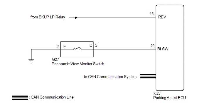
WIRING DIAGRAM
CAUTION / NOTICE / HINT
NOTICE:
- When "!" is displayed on the radio and display receiver assembly after
the cable is disconnected from the negative (-) auxiliary battery
terminal, correct the steering angle neutral point.
Click here 
- Depending on the parts that are replaced or operations that are
performed during vehicle inspection or maintenance, calibration of other
systems as well as the panoramic view monitor system may be needed.
Click here 
PROCEDURE
|
1. | CHECK DISPLAY CHECK MODE |
| (a) Check which items display on the signal check screen. |
|
|
Result | Proceed to |
|
"CAMERA SW" displays "CHK" (red) |
A |
| "CAN" displays "CHK" (red) |
B |
| "SHIFT" displays "CHK" (red) |
C |
| B |
 | GO TO CAN COMMUNICATION SYSTEM |
| C |
 | GO TO STEP 4 |
|
A |
 | |
| 2. |
CHECK HARNESS AND CONNECTOR (PANORAMIC VIEW MONITOR SWITCH - PARKING ASSIST ECU AND BODY GROUND) |
(a) Disconnect the G27 panoramic view monitor switch connector.
(b) Disconnect the K35 parking assist ECU connector.
(c) Measure the resistance according to the value(s) in the table below.
Standard Resistance:
|
Tester Connection | Condition |
Specified Condition |
|
K35-20 (BLSW) - G27-5 (D) |
Always | Below 1 Ω |
|
G27-2 (E) - Body ground |
Always | Below 1 Ω |
|
K35-20 (BLSW) or G27-5 (D) - Body ground |
Always | 10 kΩ or higher |
| NG |
 | REPAIR OR REPLACE HARNESS OR CONNECTOR |
|
OK |
 | |
| 3. |
INSPECT PANORAMIC VIEW MONITOR SWITCH |
(a) Remove the panoramic view monitor switch.
Click here

(b) Inspect the panoramic view monitor switch.
Click here 
| OK |
 | REPLACE PARKING ASSIST ECU |
| NG |
 | REPLACE PANORAMIC VIEW MONITOR SWITCH |
(a) Check that the back-up light comes on.
OK:
The back-up light comes on.
| NG |
 | GO TO LIGHTING SYSTEM (EXT) |
|
OK |
 | |
| 5. |
CHECK HARNESS AND CONNECTOR (REVERSE SIGNAL) |
(a) Disconnect the K35 parking assist ECU connector.
(b) Measure the voltage according to the value(s) in the table below.
Standard Voltage:
|
Tester Connection | Condition |
Specified Condition |
|
K35-15 (REV) - Body ground |
Power switch on (IG), shift lever in R |
11 to 14 V |
|
K35-15 (REV) - Body ground |
Power switch on (IG), shift lever not in R |
Below 1 V |
| OK |
 | REPLACE PARKING ASSIST ECU |
| NG |
 | REPAIR OR REPLACE HARNESS OR CONNECTOR |
BSM Buzzer Sound Request Signal Malfunction (C2A5C)
DESCRIPTION
This DTC is
stored when the television camera assembly receives an invalid
communication signal from the blind spot monitor sensor RH.
|
DTC No. | Detection Item |
DTC Detection Condition | Trouble Area |
DTC Output from |
|
C2A5C | BSM Buzzer Sound Request Signal Malfunction |
An invalid communication signal is received from the blind spot monitor sensor RH |
Television camera assembly |
Television camera assembly |
CAUTION / NOTICE / HINT
NOTICE:
- When "!" is displayed on the radio and display receiver assembly after
the cable is disconnected from the negative (-) auxiliary battery
terminal, correct the steering angle neutral point.
Click here 
- Depending on the parts that are replaced or operations that are
performed during vehicle inspection or maintenance, calibration of other
systems as well as the panoramic view monitor system may be needed.
Click here 
PROCEDURE
(a) Clear the DTCs.
Chassis > Parking Assist Camera > Clear DTCs
(b) Recheck for DTCs and check that no DTCs are output.
Chassis > Parking Assist Camera > Trouble Codes
|
Result | Proceed to |
|
DTC C2A5C is output | A |
|
DTC C2A5C is not output |
B |
| A |
 | REPLACE TELEVISION CAMERA ASSEMBLY |
| B |
 | END |
BSM Buzzer Malfunction (C2A5D)
DESCRIPTION
This DTC is
stored when the television camera assembly receives an RCTA buzzer
circuit malfunction signal from the blind spot monitor sensor RH.
|
DTC No. | Detection Item |
DTC Detection Condition | Trouble Area |
DTC Output from |
|
C2A5D | BSM Buzzer Malfunction |
The RCTA buzzer circuit is abnormal. |
- Blind spot monitor system
- Television camera assembly
| Television camera assembly |
CAUTION / NOTICE / HINT
NOTICE:
- When "!" is displayed on the radio and display receiver assembly after
the cable is disconnected from the negative (-) auxiliary battery
terminal, correct the steering angle neutral point.
Click here 
- Depending on the parts that are replaced or operations that are
performed during vehicle inspection or maintenance, calibration of other
systems as well as the panoramic view monitor system may be needed.
Click here 
PROCEDURE
|
1. | READ VALUE USING TECHSTREAM (BLIND SPOT MONITOR SENSOR LH STATUS) |
(a) Connect the Techstream to the DLC3.
(b) Turn the engine switch on (IG).
(c) Turn the Techstream on.
(d) Enter the following menus: Body Electrical / Blind Spot Monitor Slave / Data List.
(e) Read the Data List according to the display on the Techstream.
Body Electrical > Blind Spot Monitor Slave > Data List
|
Tester Display | Measurement Item |
Range | Normal Condition |
Diagnostic Note |
|
Buzzer Connection | Status of the buzzer connection |
Valid or Invalid | Valid: Buzzer connection is valid
Invalid: Buzzer connection is invalid |
- |
| Slave Side RCTA Function |
Switches the RCTA function on and off |
OFF or ON | OFF: RCTA function off
ON: RCTA function on |
- |
Body Electrical > Blind Spot Monitor Slave > Data List
|
Tester Display |
| Buzzer Connection |
|
Slave Side RCTA Function |
|
Result | Proceed to |
|
"Valid" and "ON" is displayed for all items. |
A |
| "Invalid" or "OFF" is displayed. |
B |
| B |
 | GO TO BLIND SPOT MONITOR SYSTEM (PROBLEM SYMPTOMS TABLE) |
|
A |
 | |
(a) Clear the DTCs.
Chassis > Parking Assist Camera > Clear DTCs
(b) Recheck for DTCs and check that no DTCs are output.
Chassis > Parking Assist Camera > Trouble Codes
|
Result | Proceed to |
|
DTC C2A5D is output | A |
|
DTC C2A5D is not output |
B |
| B |
 | REPLACE TELEVISION CAMERA ASSEMBLY |
|
A |
 | |
| 3. |
CHECK FOR DTC (BLIND SPOT MONITOR SYSTEM (C1ABE)) |
(a) Check for DTCs.
Body Electrical > Blind Spot Monitor Slave > Trouble Codes
|
Result | Proceed to |
|
DTC C1ABE is output | A |
|
DTC C1ABE is not output |
B |
| A |
 | GO TO DIAGNOSTIC TROUBLE CODE CHART (C1ABE) |
| B |
 | GO TO BLIND SPOT MONITOR SYSTEM (PROBLEM SYMPTOMS TABLE) |
Back Camera Response Malfunction (C2A6A)
DESCRIPTION
During self
diagnosis of the parking assist ECU, the parking assist ECU sends
display mode ID signals to the television camera assembly. This DTC is
stored when the output of the television camera assembly does not match
the expected output.
|
DTC No. | Detection Item |
DTC Detection Condition | Trouble Area |
DTC Output from |
|
C2A6A | Back Camera Response Malfunction |
Abnormal response from the television camera assembly |
- Television camera assembly
- Parking assist ECU
| Parking assist ECU |
CAUTION / NOTICE / HINT
NOTICE:
- When "!" is displayed on the radio and display receiver assembly after
the cable is disconnected from the negative (-) auxiliary battery
terminal, correct the steering angle neutral point.
Click here 
- Depending on the parts that are replaced or operations that are
performed during vehicle inspection or maintenance, calibration of other
systems as well as the panoramic view monitor system may be needed.
Click here 
PROCEDURE
(a) Clear the DTCs.
Chassis > Panoramic View Monitor > Clear DTCs
(b) Check for DTCs.
Chassis > Panoramic View Monitor > Trouble Codes
OK:
DTC C2A6A is not output.
| OK |
 | USE SIMULATION METHOD TO CHECK |
|
NG |
 | |
| 2. |
REPLACE TELEVISION CAMERA ASSEMBLY |
(a) Replace the television camera assembly with a new or normally functioning one.
Click here 
|
NEXT |
 | |
(a) Clear the DTCs.
Chassis > Panoramic View Monitor > Clear DTCs
(b) Check for DTCs.
Chassis > Panoramic View Monitor > Trouble Codes
OK:
DTC C2A6A is not output.
| OK |
 | END (TELEVISION CAMERA ASSEMBLY IS DEFECTIVE) |
| NG |
 | REPLACE PARKING ASSIST ECU |
Back Camera Internal Circuit (C2A63)
DESCRIPTION
This DTC is
stored when the parking assist ECU detects a signal indicating a
malfunction in the television camera assembly via CAN communication.
|
DTC No. | Detection Item |
DTC Detection Condition | Trouble Area |
DTC Output from |
|
C2A63 | Back Camera Internal Circuit |
A signal indicating a malfunction in the television camera assembly is detected. |
Television camera assembly |
Parking assist ECU |
CAUTION / NOTICE / HINT
NOTICE:
- When "!" is displayed on the radio and display receiver assembly after
the cable is disconnected from the negative (-) auxiliary battery
terminal, correct the steering angle neutral point.
Click here 
- Depending on the parts that are replaced or operations that are
performed during vehicle inspection or maintenance, calibration of other
systems as well as the panoramic view monitor system may be needed.
Click here 
PROCEDURE
(a) Clear the DTCs.
Chassis > Panoramic View Monitor > Clear DTCs
(b) Check for DTCs.
Chassis > Panoramic View Monitor > Trouble Codes
OK:
DTC C2A63 is not output.
| OK |
 | END |
| NG |
 | REPLACE TELEVISION CAMERA ASSEMBLY |
Wheel Speed Sensor Malfunction (C164D)
DESCRIPTION
- This DTC is stored when the parking assist ECU receives a wheel speed
sensor (front speed sensor RH or front speed sensor LH, rear speed
sensor RH or rear speed sensor LH) abnormality signal from the
electronically controlled brake system via CAN communication.
- This DTC is stored when the television camera assembly receives a wheel
speed sensor (front speed sensor RH or front speed sensor LH, rear speed
sensor RH or rear speed sensor LH) abnormality signal from the
electronically controlled brake system via CAN communication.
Parking Assist ECU |
DTC No. | Detection Item |
DTC Detection Condition | Trouble Area |
DTC Output from |
|
C164D | Wheel Speed Sensor Malfunction |
Wheel speed sensor malfunction |
Electronically controlled brake system |
Parking assist ECU |
Television Camera Assembly |
DTC No. | Detection Item |
DTC Detection Condition | Trouble Area |
DTC Output from |
|
C164D | Wheel Speed Sensor Malfunction |
Wheel speed sensor malfunction |
Electronically controlled brake system |
Television camera assembly |
PROCEDURE
(a) Clear the DTCs.
Chassis > Panoramic View Monitor > Clear DTCs Chassis > Parking Assist Camera > Clear DTCs
(b) Check for DTCs.
Chassis > Panoramic View Monitor > Trouble Codes Chassis > Parking Assist Camera > Trouble Codes
|
Result | Proceed to |
|
No DTCs are output | A |
|
DTC C164D is output ("Panoramic View Monitor") |
B |
| DTC C164D is output ("Parking Assist Camera") |
C |
HINT:
If
the parking assist ECU cannot read the stored information when
activated, allowing the ECU to store the information again may return
the system to normal.
HINT:
- The DTC is stored when a malfunction occurs in the electronically controlled brake system.
- If troubleshooting and repair of the malfunction in the electronically
controlled brake system have been completed, DTC C164D will not be
output again when rechecking for DTCs.
- If DTC C164D is stored frequently, duplicate the problem symptoms and
perform troubleshooting again even if the DTC is not output when
rechecking for DTCs.
Click here 
| A |
 | USE SIMULATION METHOD TO CHECK |
| B |
 | GO TO ELECTRONICALLY CONTROLLED BRAKE SYSTEM |
| C |
 | REPLACE TELEVISION CAMERA ASSEMBLY |
Vehicle Information Unmatched (C168D)
DESCRIPTION
- This DTC is stored if the parking assist ECU judges as a result of its
self check that the vehicle information received via CAN communication
and the vehicle information stored in the parking assist ECU do not
match.
- This DTC is stored if the television camera assembly judges as a result
of its self check that the vehicle information received via CAN
communication and the vehicle information stored in the parking assist
ECU do not match.
Parking Assist ECU |
DTC No. | Detection Item |
DTC Detection Condition | Trouble Area |
DTC Output from |
|
C168D | Vehicle Information Unmatched |
Vehicle information unmatched |
- Camera view adjustment (calibration)
- Steering angle setting
- Parking assist ECU
| Parking assist ECU |
Television Camera Assembly |
DTC No. | Detection Item |
DTC Detection Condition | Trouble Area |
DTC Output from |
|
C168D | Vehicle Information Unmatched |
Vehicle information unmatched |
- Back camera position setting
- Steering angle setting
- Television camera assembly
| Television camera assembly |
CAUTION / NOTICE / HINT
NOTICE:
- When "!" is displayed on the radio and display receiver assembly after
the cable is disconnected from the negative (-) auxiliary battery
terminal, correct the steering angle neutral point.
Click here 
- Depending on the parts that are replaced or operations that are
performed during vehicle inspection or maintenance, calibration of other
systems as well as the panoramic view monitor system may be needed.
Click here 
PROCEDURE
(a) Recheck for DTCs and check that no DTCs are output.
Chassis > Panoramic View Monitor > Trouble Codes Chassis > Parking Assist Camera > Trouble Codes
|
Result | Proceed to |
|
DTC C168D is output ("Parking Assist Camera") |
A |
| DTC C168D is output ("Panoramic View Monitor") |
B |
| B |
 | GO TO STEP 4 |
|
A |
 | |
| 2. |
PERFORM SETTINGS (BACK CAMERA POSITION SETTING, STEERING ANGLE SETTING) |
(a)
Perform the following procedure depending on the memory conditions to
register the vehicle information into the television camera assembly.
(1) Refer to television camera assembly optical axis adjustment (back camera position setting).
Click here 
(2) Refer to steering angle setting.
Click here 
|
NEXT |
 | |
(a) Clear the DTCs.
Chassis > Parking Assist Camera > Clear DTCs
(b) Recheck for DTCs and check that no DTCs are output.
Chassis > Parking Assist Camera > Trouble Codes
HINT:
- If DTC C168D is output, perform the procedure to register the vehicle information into the television camera assembly.
- If DTC C168D is still output after performing the procedure to register
the vehicle information into the television camera assembly 3 times,
replace the television camera assembly.
|
Result | Proceed to |
|
DTC C168D is output | A |
|
DTC C168D is not output |
B |
| A |
 | REPLACE TELEVISION CAMERA ASSEMBLY |
| B |
 | END |
| 4. |
PERFORM SETTINGS (CAMERA VIEW ADJUSTMENT [CALIBRATION], STEERING ANGLE SETTING) |
(a)
Perform the following procedure depending on the memory conditions to
register the vehicle information to the parking assist ECU.
(1) Refer to camera view adjustment (calibration).
Click here 
(2) Refer to steering angle setting.
Click here 
|
NEXT |
 | |
(a) Clear the DTCs.
Chassis > Panoramic View Monitor > Clear DTCs
(b) Check for DTCs.
Chassis > Panoramic View Monitor > Trouble Codes
OK:
DTC C168D is not output.
HINT:
- If DTC C168D is output, perform the procedure to allow the parking assist ECU to store the vehicle information again.
- If DTC C168D is still output after performing the procedure to make the
parking assist ECU store the vehicle information 3 times, replace the
parking assist ECU.
| OK |
 | END (SETTINGS ARE DEFECTIVE) |
|
NG |
 | |
| 6. |
READ VALUE USING TECHSTREAM |
(a) Connect the Techstream to the DLC3.
(b) Turn the power switch on (IG).
(c) Turn the Techstream on.
(d) Enter the following menus: Chassis / Panoramic View Monitor / Data List.
(e) Read the Data List according to the display on the Techstream.
Chassis > Panoramic View Monitor > Data List
|
Tester Display | Measurement Item |
Range | Normal Condition |
Diagnostic Note |
|
Back Camera Availability Consistency |
Status of ECU stored in television camera assembly |
OK/NG | OK: Normal
NG: Television camera assembly or parking assist ECU is abnormal |
- |
| Side Camera LH Availability Consistency |
Status of ECU stored in side television camera assembly LH |
OK/NG | OK: Normal
NG: Side television camera assembly LH or parking assist ECU is abnormal |
- |
| Front Camera Availability Consistency |
Status of ECU stored in front television camera assembly |
OK/NG | OK: Normal
NG: Front television camera assembly or parking assist ECU is abnormal |
- |
| Side Camera RH Availability Consistency |
Status of ECU stored side television camera assembly RH |
OK/NG | OK: Normal
NG: Side television camera assembly RH or parking assist ECU is abnormal |
- |
Chassis > Panoramic View Monitor > Data List
|
Tester Display |
| Back Camera Availability Consistency |
|
Side Camera LH Availability Consistency |
|
Front Camera Availability Consistency |
|
Side Camera RH Availability Consistency |
|
Result | Proceed to |
|
"NG" is displayed for any of the following items:
- Back Camera Availability Consistency
- Side Camera LH Availability Consistency
- Front Camera Availability Consistency
- Side Camera RH Availability Consistency
| A |
|
"OK" is displayed for all items. |
B |
| A |
 | ADJUST PANORAMIC VIEW MONITOR SYSTEM DISPLAY SETTING |
| B |
 | REPLACE PARKING ASSIST ECU |
ECU Malfunction (C1611)
DESCRIPTION
This DTC is stored if the television camera assembly judges that there is an internal malfunction as a result of its self check.
HINT:
The
television camera assembly stores different types of information during
initialization. If the television camera assembly cannot read the
stored information when it is activated, the television camera assembly
judges that there is an internal malfunction and stores this DTC.
|
DTC No. | Detection Item |
DTC Detection Condition | Trouble Area |
DTC Output from |
|
C1611 | ECU Malfunction |
When any of the following conditions is met:
- EEPROM status (Initial read) malfunction
- CPU communication malfunction
- Video output malfunction
| Television camera assembly |
Television camera assembly |
CAUTION / NOTICE / HINT
NOTICE:
- When "!" is displayed on the radio and display receiver assembly after
the cable is disconnected from the negative (-) auxiliary battery
terminal, correct the steering angle neutral point.
Click here 
- Depending on the parts that are replaced or operations that are
performed during vehicle inspection or maintenance, calibration of other
systems as well as the panoramic view monitor system may be needed.
Click here 
PROCEDURE
|
1. | READ VALUE USING TECHSTREAM |
(a) Connect the Techstream to the DLC3.
(b) Turn the power switch on (IG).
(c) Turn the Techstream on.
(d) Enter the following menus: Chassis / Parking Assist Camera / Data List.
(e) Read the Data List according to the display on the Techstream.
Chassis > Parking Assist Camera > Data List
|
Tester Display | Measurement Item |
Range | Normal Condition |
Diagnostic Note |
|
Video Output Status | Output condition of video signal |
OK or NG | OK: Output condition of video signal is normal
NG: Output condition of video signal is abnormal |
- |
| EEPROM Status (Initial read) |
Television camera assembly information |
OK or NG | OK: Television camera assembly normal
NG: Television camera assembly abnormal |
- |
| CPU Communication Status |
Television camera assembly information |
OK or NG | OK: Television camera assembly normal
NG: Television camera assembly abnormal |
- |
Chassis > Parking Assist Camera > Data List
|
Tester Display |
| Video Output Status |
|
EEPROM Status (Initial read) |
|
CPU Communication Status |
|
Result | Proceed to |
|
OK is displayed for all items |
A |
| NG is displayed for EEPROM status (Initial read) |
|
NG is displayed for items other than EEPROM status (Initial read) |
B |
| B |
 | REPLACE TELEVISION CAMERA ASSEMBLY |
|
A |
 | |
(a)
Perform the following procedure depending on the memory conditions to
register the vehicle information into the television camera assembly.
(1) Television camera assembly optical axis adjustment (back camera position setting).
Click here 
(2) Steering angle setting.
Click here 
|
NEXT |
 | |
(a) Clear the DTCs.
Chassis > Parking Assist Camera > Clear DTCs
(b) Recheck for DTCs and check that no DTCs are output.
Chassis > Parking Assist Camera > Trouble Codes
HINT:
- If DTC C1611 is output, perform the procedure to allow the television camera assembly to store the vehicle information again.
- If DTC C1611 is still output after performing the procedure to make the
television camera assembly store the vehicle information 3 times,
replace the television camera assembly.
|
Result | Proceed to |
|
DTC C1611 is output | A |
|
DTC C1611 is not output |
B |
| A |
 | REPLACE TELEVISION CAMERA ASSEMBLY |
| B |
 | END |
ECU Malfunction (C1614)
DESCRIPTION
This DTC is stored if the parking assist ECU judges that there is an internal malfunction as a result of its self check.
HINT:
The
parking assist ECU stores different types of information during
initialization. If the parking assist ECU cannot read the stored
information when activated, the parking assist ECU judges that there is
an internal malfunction and stores this DTC.
|
DTC No. | Detection Item |
DTC Detection Condition | Trouble Area |
DTC Output from |
|
C1614 | ECU Malfunction |
- Power source malfunction
- Main CPU start malfunction
- Main CPU reset detected
- Main CPU regular monitoring malfunction
- CAN CPU start malfunction
- System standby malfunction
- Main EEPROM malfunction
- Sub EEPROM malfunction
- ECU internal display line malfunction
| Parking assist ECU |
Parking assist ECU |
CAUTION / NOTICE / HINT
NOTICE:
- When "!" is displayed on the radio and display receiver assembly after
the cable is disconnected from the negative (-) auxiliary battery
terminal, correct the steering angle neutral point.
Click here 
- Depending on the parts that are replaced or operations that are
performed during vehicle inspection or maintenance, calibration of other
systems as well as the panoramic view monitor system may be needed.
Click here 
PROCEDURE
|
1. | READ VALUE USING TECHSTREAM (PARKING ASSIST ECU STATUS) |
(a) Use the Data List to check if the parking assist ECU status is functioning properly.
Click here 
Chassis > Panoramic View Monitor > Data List
|
Tester Display | Measurement Item |
Range | Normal Condition |
Diagnostic Note |
|
Main CPU Forced Termination Detection Record |
A
history item indicating that the main CPU did not enter standby status
within 15 seconds of turning the power switch off and a forced end was
applied | No/Yes |
No: Parking assist ECU is normal Yes: Parking assist ECU is abnormal |
- |
| Main CPU Abnormal Response Record |
A history item indicating that the main CPU became unresponsive in normal status |
No/Yes | No: Parking assist ECU is normal
Yes: Parking assist ECU is abnormal |
- |
| Main CPU Abnormal Reset Record |
A history item indicating that the main CPU was reset, although the power switch was not turned off in normal status |
No/Yes | No: Parking assist ECU is normal
Yes: Parking assist ECU is abnormal |
- |
| Image Processing IC Written Protect Record |
A history item indicating that the image processing IC memory was write protected |
No/Yes | No: Parking assist ECU is normal
Yes: Parking assist ECU is abnormal |
- |
| Image Processing IC Initialized Malfunction Record |
A history item indicating that the image processing IC memory was not initialized |
No/Yes | No: Parking assist ECU is normal
Yes: Parking assist ECU is abnormal |
- |
| Main EEPROM Access Status |
Main EEPROM access status |
Normal/Abnormal | Normal: Parking assist ECU is normal
Abnormal: Parking assist ECU is abnormal |
- |
| Sub EEPROM Access Status |
Sub-EEPROM access status |
Normal/Abnormal | Normal: Parking assist ECU is normal
Abnormal: Parking assist ECU is abnormal |
- |
| System Power Supply Voltage Malfunction Record |
A history item indicating an abnormal generated-voltage value from the system power source |
No/Yes | No: Parking assist ECU is normal
Yes: Parking assist ECU is abnormal |
- |
| Main CPU Starting Malfunction Record |
A history item indicating that the main CPU did not start |
No/Yes | No: Parking assist ECU is normal
Yes: Parking assist ECU is abnormal |
- |
| CAN CPU Boot Malfunction Record |
A
history item indicating that the CPU controlling the input and output
of the information obtained via CAN communication did not start and the
information could not be retrieved |
No/Yes | No: Parking assist ECU is normal
Yes: Parking assist ECU is abnormal |
- |
Chassis > Panoramic View Monitor > Data List
|
Tester Display |
| Main CPU Forced Termination Detection Record |
|
Main CPU Abnormal Response Record |
|
Main CPU Abnormal Reset Record |
|
Image Processing IC Written Protect Record |
|
Image Processing IC Initialized Malfunction Record |
|
Main EEPROM Access Status |
|
Sub EEPROM Access Status |
|
System Power Supply Voltage Malfunction Record |
|
Main CPU Starting Malfunction Record |
|
CAN CPU Boot Malfunction Record |
|
Result | Proceed to |
|
OK is displayed for all items |
A |
| NG is displayed |
B |
| A |
 | USE SIMULATION METHOD TO CHECK |
|
B |
 | |
(a) Clear the DTCs.
Chassis > Panoramic View Monitor > Clear DTCs
(b) Check for DTCs.
Chassis > Panoramic View Monitor > Trouble Codes
OK:
DTC C1614 is not output.
HINT:
- If DTC C1614 is output, perform the procedure to allow the parking assist ECU to store the vehicle information again.
- If DTC C1614 is still output after performing the procedure to make the
parking assist ECU store the vehicle information 3 times, replace the
parking assist ECU.
- If DTC C1614 is output frequently, replace the parking assist ECU even though the DTC is not output when rechecking for DTCs.
| OK |
 | END |
| NG |
 | REPLACE PARKING ASSIST ECU |
Back Camera Power Supply Failure (C1621)
DESCRIPTION
This DTC is
stored if the television camera assembly judges as a result of its self
check that the signals or signal lines between the television camera
assembly and parking assist ECU are not normal.
|
DTC No. | Detection Item |
DTC Detection Condition | Trouble Area |
DTC Output from |
|
C1621 | Back Camera Power Supply Failure |
Television camera assembly power supply failure |
- Harness or connector
- Television camera assembly
| Television camera assembly |
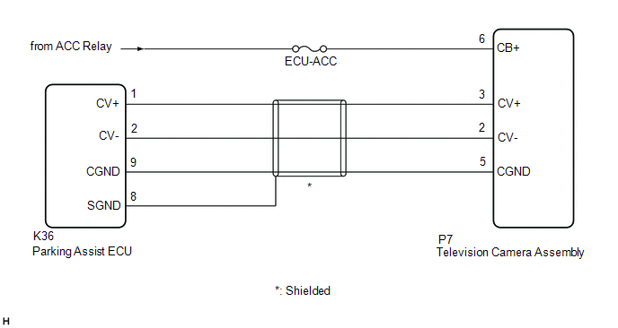
WIRING DIAGRAM
CAUTION / NOTICE / HINT
NOTICE:
- Inspect the fuses for circuits related to this system before performing the following procedure.
- When "!" is displayed on the radio and display receiver assembly after
the cable is disconnected from the negative (-) auxiliary battery
terminal, correct the steering angle neutral point.
Click here 
- Depending on the parts that are replaced or operations that are
performed during vehicle inspection or maintenance, calibration of other
systems as well as the panoramic view monitor system may be needed.
Click here 
PROCEDURE
|
1. | CHECK HARNESS AND CONNECTOR (PARKING ASSIST ECU - TELEVISION CAMERA ASSEMBLY) |
(a) Disconnect the K36 parking assist ECU connector.
(b) Disconnect the P7 television camera assembly connector.
(c) Measure the resistance according to the value(s) in the table below.
Standard Resistance:
|
Tester Connection | Condition |
Specified Condition |
|
K36-9 (CGND) - P7-5 (CGND) |
Always | Below 1 Ω |
|
K36-9 (CGND) or P7-5 (CGND) - Body ground |
Always | 10 kΩ or higher |
| NG |
 | REPAIR OR REPLACE HARNESS OR CONNECTOR |
|
OK |
 | |
| 2. |
CHECK HARNESS AND CONNECTOR (ACC POWER SUPPLY - BODY GROUND) |
(a) Measure the voltage according to the value(s) in the table below.
Standard Voltage:
|
Tester Connection | Condition |
Specified Condition |
|
P7-6 (CB+) - Body ground |
Power switch on (ACC) |
11 to 14 V |
| OK |
 | REPLACE TELEVISION CAMERA ASSEMBLY |
| NG |
 | REPAIR OR REPLACE HARNESS OR CONNECTOR |
Open or Short Circuit in Back Camera Signal (C1622)
DESCRIPTION
DTC C1622 is
stored if the parking assist ECU judges as a result of its self check
that the signals or signal lines between the parking assist ECU and the
television camera assembly are not normal.
|
DTC No. | Detection Item |
DTC Detection Condition | Trouble Area |
DTC Output from |
|
C1622 | Open or Short Circuit in Back Camera Signal |
Open or short in the rear television camera signal circuit |
- Harness or connector
- Television camera assembly
- Parking assist ECU
| Parking assist ECU |
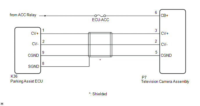
WIRING DIAGRAM
CAUTION / NOTICE / HINT
NOTICE:
- Inspect the fuses for circuits related to this system before performing the following procedure.
- When "!" is displayed on the radio and display receiver assembly after
the cable is disconnected from the negative (-) auxiliary battery
terminal, correct the steering angle neutral point.
Click here 
- Depending on the parts that are replaced or operations that are
performed during vehicle inspection or maintenance, calibration of other
systems as well as the panoramic view monitor system may be needed.
Click here 
PROCEDURE
|
1. | CHECK HARNESS AND CONNECTOR (PARKING ASSIST ECU - TELEVISION CAMERA ASSEMBLY) |
(a) Disconnect the K36 parking assist ECU connector.
(b) Disconnect the P7 television camera assembly connector.
(c) Measure the resistance according to the value(s) in the table below.
Standard Resistance:
|
Tester Connection | Condition |
Specified Condition |
|
K36-1 (CV+) - P7-3 (CV+) |
Always | Below 1 Ω |
|
K36-2 (CV-) - P7-2 (CV-) |
Always | Below 1 Ω |
|
K36-9 (CGND) - P7-5 (CGND) |
Always | Below 1 Ω |
|
K36-8 (SGND) - Body ground |
Always | 10 kΩ or higher |
|
K36-1 (CV+) or P7-3 (CV+) - Body ground |
Always | 10 kΩ or higher |
|
K36-2 (CV-) or P7-2 (CV-) - Body ground |
Always | 10 kΩ or higher |
|
K36-9 (CGND) or P7-5 (CGND) - Body ground |
Always | 10 kΩ or higher |
| NG |
 | REPAIR OR REPLACE HARNESS OR CONNECTOR |
|
OK |
 | |
| 2. |
CHECK HARNESS AND CONNECTOR (ACC POWER SUPPLY - GROUND) |
(a) Measure the voltage according to the value(s) in the table below.
Standard Voltage:
|
Tester Connection | Condition |
Specified Condition |
|
P7-6 (CB+) - Body ground |
power switch on (ACC) |
11 to 14 V |
| NG |
 | REPAIR OR REPLACE HARNESS OR CONNECTOR |
|
OK |
 | |
| 3. |
CHECK PARKING ASSIST ECU (CV-, CGND) |
(a) Disconnect the K36 parking assist ECU connector.
| (b) Measure the resistance according to the value(s) in the table below.
Standard Resistance: |
Tester Connection | Condition |
Specified Condition | |
2 (CV-) - Body ground |
Always | Below 1 Ω | |
9 (CGND) - Body ground |
Always | Below 1 Ω | |
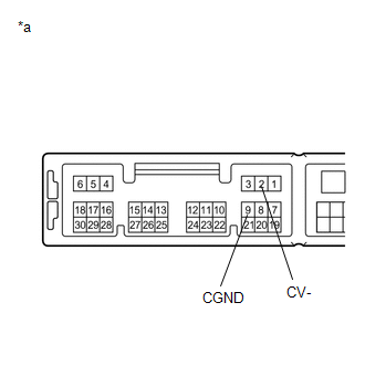 |
|
*a | Component without harness connected
(Parking Assist ECU) | | |
| NG |
 | REPLACE PARKING ASSIST ECU |
|
OK |
 | |
| 4. |
CHECK TELEVISION CAMERA ASSEMBLY (CV+, CGND) |
(a) Remove the parking assist ECU with the connector still connected.
(b) Using an oscilloscope, check the waveform of the television camera assembly.
HINT:
A
waterproof connector is used for the television camera assembly.
Therefore, inspect the waveform at the parking assist ECU with the
connector connected.
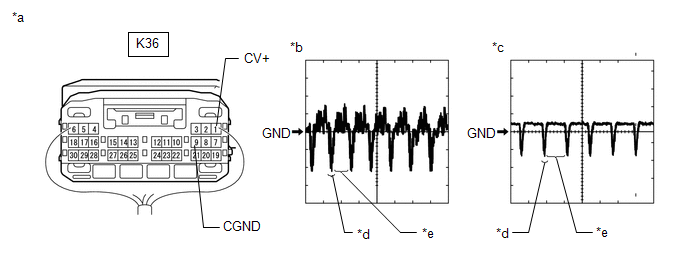
|
*a | Component with harness connected
(Parking Assist ECU) | *b |
Waveform 1 (camera lens not covered, displaying an image) |
|
*c | Waveform 2 (camera lens covered, blacking out the screen) |
*d | Synchronization Signal |
|
*e | Video Waveform |
- | - |
HINT:
- The video waveform changes according to the image sent by the television camera assembly.
- The video waveform is constantly output when the power switch is on (ACC).
Measurement Condition |
Item | Content |
|
Terminal No. (Symbol) |
K36-1 (CV+) - K36-9 (CGND) |
|
Tool Setting | 200 mV/DIV., 50 ÎĽsec./DIV. |
|
Condition | Power switch on (IG), panoramic view monitor system operating |
OK:
Waveform is similar to that shown in the illustration.
| OK |
 | REPLACE PARKING ASSIST ECU |
| NG |
 | REPLACE TELEVISION CAMERA ASSEMBLY |
Open or Short in Steering Angle Sensor +B (C1625)
DESCRIPTION
- This DTC is stored if the parking assist ECU receives a signal via CAN
communication from the steering sensor that indicates a power supply
system problem.
- This DTC is stored if the television camera assembly receives a signal
via CAN communication from the steering sensor that indicates a power
supply system problem.
Parking Assist ECU |
DTC No. | Detection Item |
DTC Detection Condition | Trouble Area |
DTC Output from |
|
C1625 | Open or Short in Steering Angle Sensor +B |
Open or short in steering angle sensor +B |
- Harness or connector
- Steering sensor
| Parking assist ECU |
Television Camera Assembly |
DTC No. | Detection Item |
DTC Detection Condition | Trouble Area |
DTC Output from |
|
C1625 | Open or Short in Steering Angle Sensor +B |
Open or short in steering angle sensor +B |
- Harness or connector
- Steering sensor
| Television camera assembly |
WIRING DIAGRAM
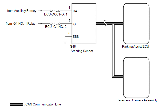
CAUTION / NOTICE / HINT
NOTICE:
- Since the panoramic view monitor system has functions that use the CAN
communication system, first check that there is no malfunction in the
communication system by inspecting the CAN communication functions in
accordance with the "How to Proceed with Troubleshooting" procedures.
Then, conduct the following inspection procedure.
- When "!" is displayed on the radio and display receiver assembly after
the cable is disconnected from the negative (-) auxiliary battery
terminal, correct the steering angle neutral point.
Click here 
- Depending on the parts that are replaced or operations that are
performed during vehicle inspection or maintenance, calibration of other
systems as well as the panoramic view monitor system may be needed.
Click here 
- Inspect the fuses for circuits related to this system before performing the following procedure.
PROCEDURE
|
1. | CHECK HARNESS AND CONNECTOR (STEERING SENSOR POWER SOURCE) |
(a) Disconnect the G48 steering sensor connector.
Click here

(b) Measure the resistance according to the value(s) in the table below.
Standard Resistance:
|
Tester Connection | Condition |
Specified Condition |
|
G48-6 (ESS) - Body ground |
Always | Below 1 Ω |
(c) Measure the voltage according to the value(s) in the table below.
Standard Voltage:
|
Tester Connection | Condition |
Specified Condition |
|
G48-9 (IG) - G48-6 (ESS) |
Power switch on (IG) |
11 to 14 V |
|
G48-4 (BAT) - G48-6 (ESS) |
Always | 11 to 14 V |
| OK |
 | REPLACE STEERING SENSOR |
| NG |
 | REPAIR OR REPLACE HARNESS OR CONNECTOR |
Steering Angle Sensor Failure (C1626)
DESCRIPTION
- This DTC is stored if the parking assist ECU receives a signal via CAN
communication from the steering sensor that indicates an internal
malfunction.
- This DTC is stored if the television camera assembly receives a signal
via CAN communication from the steering sensor that indicates an
internal malfunction.
Parking Assist ECU |
DTC No. | Detection Item |
DTC Detection Condition | Trouble Area |
DTC Output from |
|
C1626 | Steering Angle Sensor Failure |
A fail flag is transmitted from the steering angle sensor |
- Steering sensor
- Parking assist ECU
| Parking assist ECU |
Television Camera Assembly |
DTC No. | Detection Item |
DTC Detection Condition | Trouble Area |
DTC Output from |
|
C1626 | Steering Angle Sensor Failure |
A fail flag is transmitted from the steering angle sensor |
- Steering sensor
- Television camera assembly
| Television camera assembly |
CAUTION / NOTICE / HINT
NOTICE:
- When "!" is displayed on the radio and display receiver assembly after
the cable is disconnected from the negative (-) auxiliary battery
terminal, correct the steering angle neutral point.
Click here 
- Depending on the parts that are replaced or operations that are
performed during vehicle inspection or maintenance, calibration of other
systems as well as the panoramic view monitor system may be needed.
Click here 
- The vehicle is equipped with a Supplemental Restraint System (SRS) which
includes components such as airbags. Before servicing (including
removal or installation of parts), be sure to read the precaution for
Supplemental Restraint System.
Click here 
PROCEDURE
(a) Clear the DTCs.
Chassis > Panoramic View Monitor > Clear DTCs Chassis > Parking Assist Camera > Clear DTCs
(b) Recheck for DTCs and check that no DTCs are output.
Chassis > Panoramic View Monitor > Trouble Codes Chassis > Parking Assist Camera > Trouble Codes
|
Result | Proceed to |
|
DTC C1626 is output | A |
|
DTC C1626 is not output |
B |
| B |
 | USE SIMULATION METHOD TO CHECK |
|
A |
 | |
| 2. |
REPLACE STEERING SENSOR |
(a) Replace the steering sensor with a normally functioning one.
Click here 
|
NEXT |
 | |
(a) Clear the DTCs.
Chassis > Panoramic View Monitor > Clear DTCs Chassis > Parking Assist Camera > Clear DTCs
(b) Check for DTCs.
Chassis > Panoramic View Monitor > Trouble Codes Chassis > Parking Assist Camera > Trouble Codes
|
Result | Proceed to |
|
No DTCs are output | A |
|
DTC C1626 is output ("Panoramic View Monitor") |
B |
| DTC C1626 is output ("Parking Assist Camera") |
C |
| A |
 | END (STEERING SENSOR WAS DEFECTIVE) |
| B |
 | REPLACE PARKING ASSIST ECU |
| C |
 | REPLACE TELEVISION CAMERA ASSEMBLY |
Front Camera Feedback Malfunction (C1681)
DESCRIPTION
DTC C1681 is
stored if the parking assist ECU judges as a result of its self check
that a synchronization problem is occurring in the image signal sent
from the front television camera assembly to the parking assist ECU .
|
DTC No. | Detection Item |
DTC Detection Condition | Trouble Area |
DTC Output from |
|
C1681 | Front Camera Feedback Malfunction |
Front television camera power supply failure |
- Harness or connector
- Front television camera assembly
- Parking assist ECU
| Parking assist ECU |
WIRING DIAGRAM
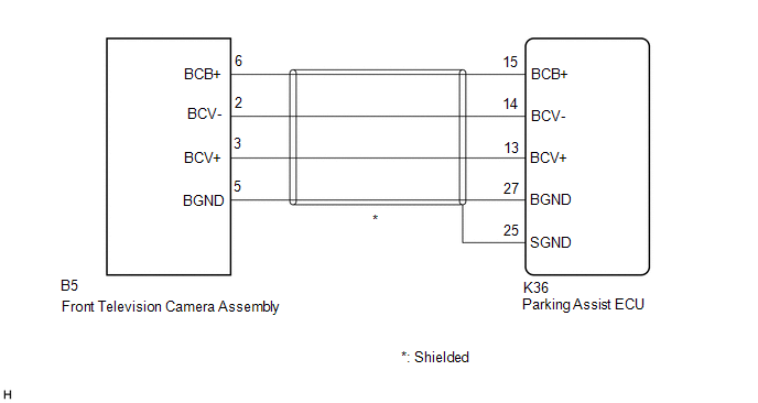
CAUTION / NOTICE / HINT
NOTICE:
- When "!" is displayed on the radio and display receiver assembly after
the cable is disconnected from the negative (-) auxiliary battery
terminal, correct the steering angle neutral point.
Click here 
- Depending on the parts that are replaced or operations that are
performed during vehicle inspection or maintenance, calibration of other
systems as well as the panoramic view monitor system may be needed.
Click here 
PROCEDURE
|
1. | CHECK HARNESS AND CONNECTOR (PARKING ASSIST ECU - FRONT TELEVISION CAMERA ASSEMBLY) |
(a) Disconnect the K36 parking assist ECU connector.
(b) Disconnect the B5 front television camera assembly connector.
(c) Measure the resistance according to the value(s) in the table below.
Standard Resistance:
|
Tester Connection | Condition |
Specified Condition |
|
K36-15 (BCB+) - B5-6 (BCB+) |
Always | Below 1 Ω |
|
K36-13 (BCV+) - B5-3 (BCV+) |
Always | Below 1 Ω |
|
K36-14 (BCV-) - B5-2 (BCV-) |
Always | Below 1 Ω |
|
K36-27 (BGND) - B5-5 (BGND) |
Always | Below 1 Ω |
|
K36-25 (SGND) - Body ground |
Always | 10 kΩ or higher |
|
K36-15 (BCB+) or B5-6 (BCB+) - Body ground |
Always | 10 kΩ or higher |
|
K36-13 (BCV+) or B5-3 (BCV+) - Body ground |
Always | 10 kΩ or higher |
|
K36-14 (BCV-) or B5-2 (BCV-) - Body ground |
Always | 10 kΩ or higher |
|
K36-27 (BGND) or B5-5 (BGND) - Body ground |
Always | 10 kΩ or higher |
| NG |
 | REPAIR OR REPLACE HARNESS OR CONNECTOR |
|
OK |
 | |
| 2. |
CHECK PARKING ASSIST ECU (BCV-, BGND) |
(a) Disconnect the K36 parking assist ECU connector.
| (b) Measure the resistance according to the value(s) in the table below.
Standard Resistance: |
Tester Connection | Condition |
Specified Condition | |
27 (BGND) - Body ground |
Always | Below 1 Ω | |
14 (BCV-) - Body ground |
Always | Below 1 Ω | |
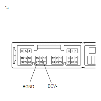 |
|
*a | Component without harness connected
(Parking Assist ECU) | | |
| NG |
 | REPLACE PARKING ASSIST ECU |
|
OK |
 | |
| 3. |
CHECK PARKING ASSIST ECU (BCB+, BGND) |
| (a) Remove the parking assist ECU with the connector still connected. |
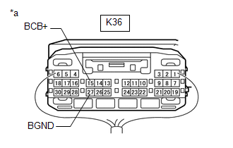 |
|
*a | Component with harness connected
(Parking Assist ECU) | | |
(b) Measure the resistance according to the value(s) in the table below.
Standard Resistance:
|
Tester Connection | Condition |
Specified Condition |
|
K36-27 (BGND) - Body ground |
Always | Below 1 Ω |
(c) Measure the voltage according to the value(s) in the table below.
Standard Voltage:
|
Tester Connection | Condition |
Specified Condition |
|
K36-15 (BCB+) - K36-27 (BGND) |
Power switch on (ACC) |
5.5 to 7.05 V |
| NG |
 | REPLACE PARKING ASSIST ECU |
|
OK |
 | |
| 4. |
CHECK FRONT TELEVISION CAMERA ASSEMBLY (BCV+, BGND) |
(a) Remove the parking assist ECU with the connector still connected.
(b) Using an oscilloscope, check the waveform of the front television camera assembly.
HINT:
A
waterproof connector is used for the front television camera assembly.
Therefore, inspect the waveform at the parking assist ECU with the
connector connected.
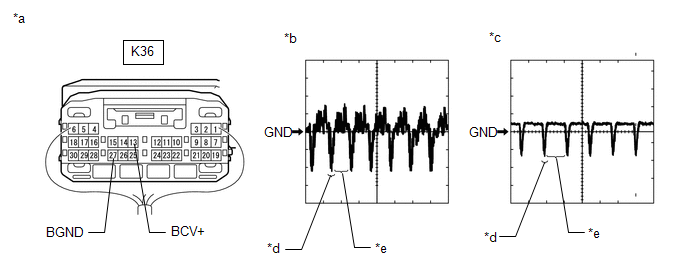
|
*a | Component with harness connected
(Parking Assist ECU) | *b |
Waveform 1 (camera lens not covered, displaying an image) |
|
*c | Waveform 2 (camera lens covered, blacking out the screen) |
*d | Synchronization Signal |
|
*e | Video Waveform |
- | - |
HINT:
- The video waveform changes according to the image sent by the front television camera assembly.
- The video waveform is constantly output when the power switch is on (ACC).
Measurement Condition |
Item | Content |
|
Terminal No. (Symbol) |
K36-13 (BCV+) - K36-27 (BGND) |
|
Tool Setting | 200 mV/DIV., 50 ÎĽsec./DIV. |
|
Condition | Power switch on (IG), panoramic view monitor system operating |
OK:
Waveform is similar to that shown in the illustration.
| OK |
 | REPLACE PARKING ASSIST ECU |
| NG |
 | REPLACE FRONT TELEVISION CAMERA ASSEMBLY |
Front Camera Current Malfunction (C1682)
DESCRIPTION
DTC C1682 is
stored if the parking assist ECU judges as a result of its self check
that there is a problem with the current supplied from the front
television camera assembly connected to the parking assist ECU.
|
DTC No. | Detection Item |
DTC Detection Condition | Trouble Area |
DTC Output from |
|
C1682 | Front Camera Current Malfunction |
Open or short in the front television camera signal circuit |
- Harness or connector
- Front television camera assembly
- Parking assist ECU
| Parking assist ECU |
WIRING DIAGRAM
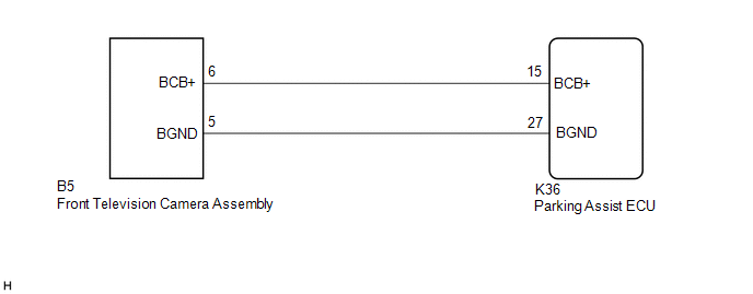
CAUTION / NOTICE / HINT
NOTICE:
- When "!" is displayed on the radio and display receiver assembly after
the cable is disconnected from the negative (-) auxiliary battery
terminal, correct the steering angle neutral point.
Click here 
- Depending on the parts that are replaced or operations that are
performed during vehicle inspection or maintenance, calibration of other
systems as well as the panoramic view monitor system may be needed.
Click here 
PROCEDURE
|
1. | CHECK HARNESS AND CONNECTOR (PARKING ASSIST ECU - FRONT TELEVISION CAMERA ASSEMBLY) |
(a) Disconnect the K36 parking assist ECU connector.
(b) Disconnect the B5 front television camera assembly connector.
(c) Measure the resistance according to the value(s) in the table below.
Standard Resistance:
|
Tester Connection | Condition |
Specified Condition |
|
K36-15 (BCB+) - B5-6 (BCB+) |
Always | Below 1 Ω |
|
K36-27 (BGND) - B5-5 (BGND) |
Always | Below 1 Ω |
|
K36-15 (BCB+) or B5-6 (BCB+) - Body ground |
Always | 10 kΩ or higher |
|
K36-27 (BGND) or B5-5 (BGND) - Body ground |
Always | 10 kΩ or higher |
| NG |
 | REPAIR OR REPLACE HARNESS OR CONNECTOR |
|
OK |
 | |
| 2. |
CHECK PARKING ASSIST ECU (BCB+, BGND) |
| (a) Remove the parking assist ECU with the connector still connected. |
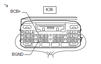 |
|
*a | Component with harness connected
(Parking Assist ECU) | | |
(b) Measure the resistance according to the value(s) in the table below.
Standard Resistance:
|
Tester Connection | Condition |
Specified Condition |
|
K36-27 (BGND) - Body ground |
Always | Below 1 Ω |
(c) Measure the voltage according to the value(s) in the table below.
Standard Voltage:
|
Tester Connection | Condition |
Specified Condition |
|
K36-15 (BCB+) - K36-27 (BGND) |
Power switch on (ACC) |
5.5 to 7.05 V |
| OK |
 | REPLACE FRONT TELEVISION CAMERA ASSEMBLY |
| NG |
 | REPLACE PARKING ASSIST ECU |
Side Camera Feedback Malfunction (C1683)
DESCRIPTION
This DTC is
stored if the parking assist ECU judges as a result of its self check
that a synchronization problem is occurring in the image signal sent
from the passenger side television camera assembly to the parking assist
ECU.
|
DTC No. | Detection Item |
DTC Detection Condition | Trouble Area |
DTC Output from |
|
C1683 | Side Camera Feedback Malfunction |
Side camera feedback malfunction |
- Harness or connector
- Parking assist ECU
- Side television camera assembly RH
- Outer rear view mirror assembly RH
| Parking assist ECU |
WIRING DIAGRAM
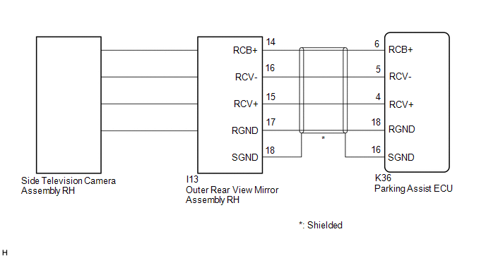
CAUTION / NOTICE / HINT
NOTICE:
- When "!" is displayed on the radio and display receiver assembly after
the cable is disconnected from the negative (-) auxiliary battery
terminal, correct the steering angle neutral point.
Click here 
- Depending on the parts that are replaced or operations that are
performed during vehicle inspection or maintenance, calibration of other
systems as well as the panoramic view monitor system may be needed.
Click here 
PROCEDURE
(a) Clear the DTCs.
Chassis > Panoramic View Monitor > Clear DTCs
(b) Check for DTCs.
Chassis > Panoramic View Monitor > Trouble Codes
OK:
DTC C1683 is not output.
| OK |
 | USE SIMULATION METHOD TO CHECK |
|
NG |
 | |
| 2. |
CHECK HARNESS AND CONNECTOR (PARKING ASSIST ECU - OUTER REAR VIEW MIRROR ASSEMBLY RH) |
(a) Disconnect the K36 parking assist ECU connector.
(b) Disconnect the I13 outer rear view mirror assembly RH connector.
(c) Measure the resistance according to the value(s) in the table below.
Standard Resistance:
|
Tester Connection | Condition |
Specified Condition |
|
K36-6 (RCB+) - I13-14 (RCB+) |
Always | Below 1 Ω |
|
K36-4 (RCV+) - I13-15 (RCV+) |
Always | Below 1 Ω |
|
K36-5 (RCV-) - I13-16 (RCV-) |
Always | Below 1 Ω |
|
K36-18 (RGND) - I13-17 (RGND) |
Always | Below 1 Ω |
|
K36-16 (SGND) - I13-18 (SGND) |
Always | Below 1 Ω |
|
K36-6 (RCB+) or I13-14 (RCB+) - Body ground |
Always | 10 kΩ or higher |
|
K36-4 (RCV+) or I13-15 (RCV+) - Body ground |
Always | 10 kΩ or higher |
|
K36-5 (RCV-) or I13-16 (RCV-) - Body ground |
Always | 10 kΩ or higher |
|
K36-18 (RGND) or I13-17 (RGND) - Body ground |
Always | 10 kΩ or higher |
|
K36-16 (SGND) or I13-18 (SGND) - Body ground |
Always | 10 kΩ or higher |
| NG |
 | REPAIR OR REPLACE HARNESS OR CONNECTOR |
|
OK |
 | |
| 3. |
CHECK PARKING ASSIST ECU (RCV-, RGND) |
(a) Disconnect the K36 parking assist ECU connector.
| (b) Measure the resistance according to the value(s) in the table below.
Standard Resistance: |
Tester Connection | Condition |
Specified Condition | |
18 (RGND) - Body ground |
Always | Below 1 Ω | |
5 (RCV-) - Body ground |
Always | Below 1 Ω | |
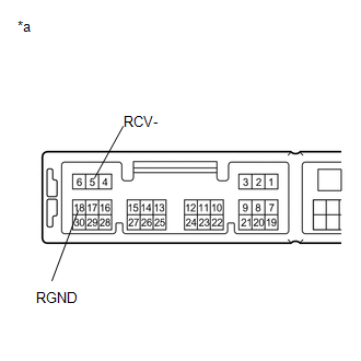 |
|
*a | Component without harness connected
(Parking Assist ECU) | | |
| NG |
 | REPLACE PARKING ASSIST ECU |
|
OK |
 | |
| 4. |
CHECK PARKING ASSIST ECU (RCB+, RGND) |
| (a) Remove the parking assist ECU with the connector still connected. |
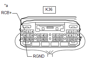 |
|
*a | Component with harness connected
(Parking Assist ECU) | | |
(b) Measure the resistance according to the value(s) in the table below.
Standard Resistance:
|
Tester Connection | Condition |
Specified Condition |
|
K36-18 (RGND) - Body ground |
Always | Below 1 Ω |
(c) Measure the voltage according to the value(s) in the table below.
Standard Voltage:
|
Tester Connection | Condition |
Specified Condition |
|
K36-6 (RCB+) - K36-18 (RGND) |
Power switch on (ACC) |
5.5 to 7.05 V |
| NG |
 | REPLACE PARKING ASSIST ECU |
|
OK |
 | |
| 5. |
CHECK SIDE TELEVISION CAMERA ASSEMBLY RH (RCV+, RGND) |
(a) Remove the parking assist ECU with the connector still connected.
(b) Using an oscilloscope, check the waveform of the side television camera assembly RH.
HINT:
A
waterproof connector is used for the side television camera assembly
RH. Therefore, inspect the waveform at the parking assist ECU with the
connector connected.
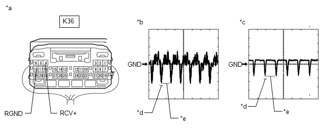
|
*a | Component with harness connected
(Parking Assist ECU) | *b |
Waveform 1 (camera lens not covered, displaying an image) |
|
*c | Waveform 2 (camera lens covered, blacking out the screen) |
*d | Synchronization Signal |
|
*e | Video Waveform |
- | - |
HINT:
- The video waveform changes according to the image sent by the side television camera assembly RH.
- The video waveform is constantly output when the power switch is on (ACC).
Measurement Condition |
Item | Content |
|
Tester Connection | K36-4 (RCV+) - K36-18 (RGND) |
|
Tool Setting | 200 mV/DIV., 50 ÎĽsec./DIV. |
|
Condition | Power switch on (IG), panoramic view monitor system operating |
OK:
Waveform is similar to that shown in illustration.
| OK |
 | REPLACE PARKING ASSIST ECU |
|
NG |
 | |
| 6. |
REPLACE SIDE TELEVISION CAMERA ASSEMBLY RH |
(a) Replace the side television camera assembly RH with a new or normally functioning one.
Click here 
|
NEXT |
 | |
(a) Clear the DTCs.
Chassis > Panoramic View Monitor > Clear DTCs
(b) Check for DTCs.
Chassis > Panoramic View Monitor > Trouble Codes
OK:
DTC C1683 is not output.
| OK |
 | END (SIDE TELEVISION CAMERA ASSEMBLY RH IS DEFECTIVE) |
| NG |
 | REPLACE OUTER REAR VIEW MIRROR ASSEMBLY RH |
Side Camera Current Malfunction (C1684)
DESCRIPTION
This DTC is
stored if the parking assist ECU judges as a result of its self check
that a synchronization problem is occurring in the image signal sent
from the passenger side television camera assembly to the parking assist
ECU.
|
DTC No. | Detection Item |
DTC Detection Condition | Trouble Area |
DTC Output from |
|
C1684 | Side Camera Current Malfunction |
Side camera current malfunction |
- Harness or connector
- Parking assist ECU
- Side television camera assembly RH
- Outer rear view mirror assembly RH
| Parking assist ECU |
WIRING DIAGRAM
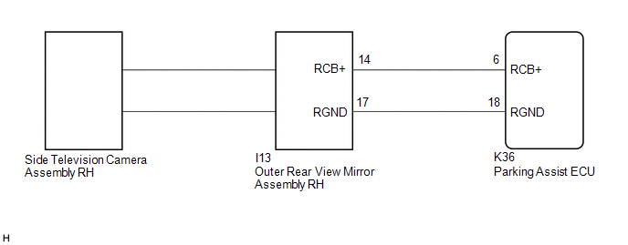
CAUTION / NOTICE / HINT
NOTICE:
- When "!" is displayed on the radio and display receiver assembly after
the cable is disconnected from the negative (-) auxiliary battery
terminal, correct the steering angle neutral point.
Click here 
- Depending on the parts that are replaced or operations that are
performed during vehicle inspection or maintenance, calibration of other
systems as well as the panoramic view monitor system may be needed.
Click here 
PROCEDURE
(a) Clear the DTCs.
Chassis > Panoramic View Monitor > Clear DTCs
(b) Check for DTCs.
Chassis > Panoramic View Monitor > Trouble Codes
OK:
DTC C1684 is not output.
| OK |
 | USE SIMULATION METHOD TO CHECK |
|
NG |
 | |
| 2. |
CHECK HARNESS AND CONNECTOR (PARKING ASSIST ECU - OUTER REAR VIEW MIRROR ASSEMBLY RH) |
(a) Disconnect the K36 parking assist ECU connector.
(b) Disconnect the I13 outer rear view mirror assembly RH connector.
(c) Measure the resistance according to the value(s) in the table below.
Standard Resistance:
|
Tester Connection | Condition |
Specified Condition |
|
K36-6 (RCB+) - I13-14 (RCB+) |
Always | Below 1 Ω |
|
K36-18 (RGND) - I13-17 (RGND) |
Always | Below 1 Ω |
|
K36-6 (RCB+) or I13-14 (RCB+) - Body ground |
Always | 10 kΩ or higher |
|
K36-18 (RGND) or I13-17 (RGND) - Body ground |
Always | 10 kΩ or higher |
| NG |
 | REPAIR OR REPLACE HARNESS OR CONNECTOR |
|
OK |
 | |
| 3. |
CHECK PARKING ASSIST ECU (RCB+, RGND) |
| (a) Remove the parking assist ECU with the connector still connected. |
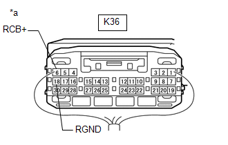 |
|
*a | Component with harness connected
(Parking Assist ECU) | | |
(b) Measure the resistance according to the value(s) in the table below.
Standard Resistance:
|
Tester Connection | Condition |
Specified Condition |
|
K36-18 (RGND) - Body ground |
Always | Below 1 Ω |
(c) Measure the voltage according to the value(s) in the table below.
Standard Voltage:
|
Tester Connection | Condition |
Specified Condition |
|
K36-6 (RCB+) - K36-18 (RGND) |
Power switch on (ACC) |
5.5 to 7.05 V |
| NG |
 | REPLACE PARKING ASSIST ECU |
|
OK |
 | |
| 4. |
REPLACE SIDE TELEVISION CAMERA ASSEMBLY RH |
(a) Replace the side television camera assembly RH with a new or normally functioning one.
Click here 
|
NEXT |
 | |
(a) Clear the DTCs.
Chassis > Panoramic View Monitor > Clear DTCs
(b) Check for DTCs.
Chassis > Panoramic View Monitor > Trouble Codes
OK:
DTCs C1684 is not output.
| OK |
 | END (SIDE TELEVISION CAMERA ASSEMBLY RH IS DEFECTIVE) |
| NG |
 | REPLACE OUTER REAR VIEW MIRROR ASSEMBLY RH |
Driver Side Camera Video Sync Signal Malfunction (C1686)
DESCRIPTION
This DTC is
stored if the parking assist ECU judges as a result of its self check
that a synchronization problem is occurring in the image signal sent
from the driver side television camera assembly to the parking assist
ECU.
|
DTC No. | Detection Item |
DTC Detection Condition | Trouble Area |
DTC Output from |
|
C1686 | Driver Side Camera Video Sync Signal Malfunction |
Side camera feedback malfunction |
- Harness or connector
- Parking assist ECU
- Side television camera assembly LH
- Outer rear view mirror assembly LH
| Parking assist ECU |
WIRING DIAGRAM
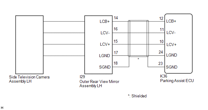
CAUTION / NOTICE / HINT
NOTICE:
- When "!" is displayed on the radio and display receiver assembly after
the cable is disconnected from the negative (-) auxiliary battery
terminal, correct the steering angle neutral point.
- Depending on the parts that are replaced or operations that are
performed during vehicle inspection or maintenance, calibration of other
systems as well as the panoramic view monitor system may be needed.
Click here 
PROCEDURE
(a) Clear the DTCs.
Chassis > Panoramic View Monitor > Clear DTCs
(b) Check for DTCs.
Chassis > Panoramic View Monitor > Trouble Codes
OK:
DTC C1686 is not output.
| OK |
 | USE SIMULATION METHOD TO CHECK |
|
NG |
 | |
| 2. |
CHECK HARNESS AND CONNECTOR (PARKING ASSIST ECU - OUTER REAR VIEW MIRROR ASSEMBLY LH) |
(a) Disconnect the K36 parking assist ECU connector.
(b) Disconnect the I29 outer rear view mirror assembly LH connector.
(c) Measure the resistance according to the value(s) in the table below.
Standard Resistance:
|
Tester Connection | Condition |
Specified Condition |
|
K36-12 (LCB+) - I29-14 (LCB+) |
Always | Below 1 Ω |
|
K36-10 (LCV+) - I29-15 (LCV+) |
Always | Below 1 Ω |
|
K36-11 (LCV-) - I29-16 (LCV-) |
Always | Below 1 Ω |
|
K36-24 (LGND) - I29-17 (LGND) |
Always | Below 1 Ω |
|
K36-23 (SGND) - I29-18 (SGND) |
Always | Below 1 Ω |
|
K36-12 (LCB+) or I29-14 (LCB+) - Body ground |
Always | 10 kΩ or higher |
|
K36-10 (LCV+) or I29-15 (LCV+) - Body ground |
Always | 10 kΩ or higher |
|
K36-11 (LCV-) or I29-16 (LCV-) - Body ground |
Always | 10 kΩ or higher |
|
K36-24 (LGND) or I29-17 (LGND) - Body ground |
Always | 10 kΩ or higher |
|
K36-23 (SGND) or I29-18 (SGND) - Body ground |
Always | 10 kΩ or higher |
| NG |
 | REPAIR OR REPLACE HARNESS OR CONNECTOR |
|
OK |
 | |
| 3. |
CHECK PARKING ASSIST ECU (LCV-, LGND) |
(a) Disconnect the K36 parking assist ECU connector.
| (b) Measure the resistance according to the value(s) in the table below.
Standard Resistance: |
Tester Connection | Condition |
Specified Condition | |
24 (LGND) - Body ground |
Always | Below 1 Ω | |
11 (LCV-) - Body ground |
Always | Below 1 Ω | |
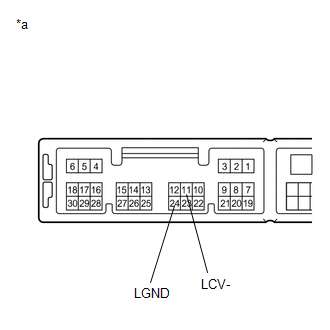 |
|
*a | Component without harness connected
(Parking Assist ECU) | | |
| NG |
 | REPLACE PARKING ASSIST ECU |
|
OK |
 | |
| 4. |
CHECK PARKING ASSIST ECU (LCB+, LGND) |
| (a) Remove the parking assist ECU with the connector still connected. |
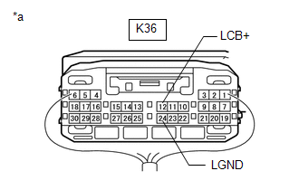 |
|
*a | Component with harness connected
(Parking Assist ECU) | | |
(b) Measure the resistance according to the value(s) in the table below.
Standard Resistance:
|
Tester Connection | Condition |
Specified Condition |
|
K36-24 (LGND) - Body ground |
Always | Below 1 Ω |
(c) Measure the voltage according to the value(s) in the table below.
Standard Voltage:
|
Tester Connection | Condition |
Specified Condition |
|
K36-12 (LCB+) - K36-24 (LGND) |
Power switch on (ACC) |
5.5 to 7.05 V |
| NG |
 | REPLACE PARKING ASSIST ECU |
|
OK |
 | |
| 5. |
CHECK SIDE TELEVISION CAMERA ASSEMBLY LH (LCV+, LGND) |
(a) Remove the parking assist ECU with the connector still connected.
(b) Using an oscilloscope, check the waveform of the side television camera assembly LH.
HINT:
A
waterproof connector is used for the side television camera assembly
LH. Therefore, inspect the waveform at the parking assist ECU with the
connector connected.
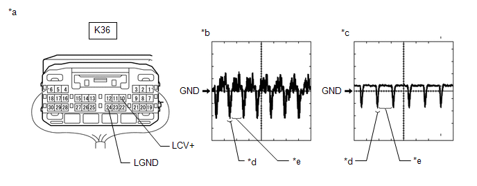
|
*a | Component with harness connected
(Parking Assist ECU) | *b |
Waveform 1 (camera lens not covered, displaying an image) |
|
*c | Waveform 2 (camera lens covered, blacking out the screen) |
*d | Synchronization Signal |
|
*e | Video Waveform |
- | - |
HINT:
- The video waveform changes according to the image sent by the side television camera assembly LH.
- The video waveform is constantly output when the power switch is on (ACC).
Measurement Condition |
Item | Content |
|
Tester Connection | K36-10 (LCV+) - K36-24 (LGND) |
|
Tool Setting | 200 mV/DIV., 50 ÎĽsec./DIV. |
|
Condition | Power switch on (IG), panoramic view monitor system operating |
OK:
Waveform is similar to that shown in illustration.
| OK |
 | REPLACE PARKING ASSIST ECU |
|
NG |
 | |
| 6. |
REPLACE SIDE TELEVISION CAMERA ASSEMBLY LH |
(a) Replace the side television camera assembly LH with a new or normally functioning one.
Click here 
|
NEXT |
 | |
(a) Clear the DTCs.
Chassis > Panoramic View Monitor > Clear DTCs
(b) Check for DTCs.
Chassis > Panoramic View Monitor > Trouble Codes
OK:
DTC C1686 is not output.
| OK |
 | END (SIDE TELEVISION CAMERA ASSEMBLY LH IS DEFECTIVE) |
| NG |
 | REPLACE OUTER REAR VIEW MIRROR ASSEMBLY LH |
Over Current Detected in Driver Side Camera (C1687)
DESCRIPTION
This DTC is
stored if the parking assist ECU judges as a result of its self check
that a synchronization problem is occurring in the image signal sent
from the driver side television camera assembly to the parking assist
ECU.
|
DTC No. | Detection Item |
DTC Detection Condition | Trouble Area |
DTC Output from |
|
C1687 | Over Current Detected in Driver Side Camera |
Side camera current malfunction |
- Harness or connector
- Parking assist ECU
- Side television camera assembly LH
- Outer rear view mirror assembly LH
| Parking assist ECU |
WIRING DIAGRAM
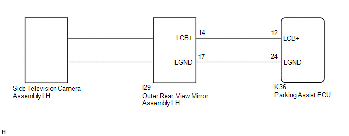
CAUTION / NOTICE / HINT
NOTICE:
- When "!" is displayed on the radio and display receiver assembly after
the cable is disconnected from the negative (-) auxiliary battery
terminal, correct the steering angle neutral point.
Click here 
- Depending on the parts that are replaced or operations that are
performed during vehicle inspection or maintenance, calibration of other
systems as well as the panoramic view monitor system may be needed.
Click here 
PROCEDURE
(a) Clear the DTCs.
Chassis > Panoramic View Monitor > Clear DTCs
(b) Check for DTCs.
Chassis > Panoramic View Monitor > Trouble Codes
OK:
DTC C1687 is not output.
| OK |
 | USE SIMULATION METHOD TO CHECK |
|
NG |
 | |
| 2. |
CHECK HARNESS AND CONNECTOR (PARKING ASSIST ECU - OUTER REAR VIEW MIRROR ASSEMBLY LH) |
(a) Disconnect the K36 parking assist ECU connector.
(b) Disconnect the I29 outer rear view mirror assembly LH connector.
(c) Measure the resistance according to the value(s) in the table below.
Standard Resistance:
|
Tester Connection | Condition |
Specified Condition |
|
K36-12 (LCB+) - I29-14 (LCB+) |
Always | Below 1 Ω |
|
K36-24 (LGND) - I29-17 (LGND) |
Always | Below 1 Ω |
|
K36-12 (LCB+) or I29-14 (LCB+) - Body ground |
Always | 10 kΩ or higher |
|
K36-24 (LGND) or I29-17 (LGND) - Body ground |
Always | 10 kΩ or higher |
| NG |
 | REPAIR OR REPLACE HARNESS OR CONNECTOR |
|
OK |
 | |
| 3. |
CHECK PARKING ASSIST ECU (LCB+, LGND) |
| (a) Remove the parking assist ECU with the connector still connected. |
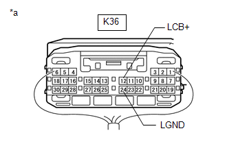 |
|
*a | Component with harness connected
(Parking Assist ECU) | | |
(b) Measure the resistance according to the value(s) in the table below.
Standard Resistance:
|
Tester Connection | Condition |
Specified Condition |
|
K36-24 (LGND) - Body ground |
Always | Below 1 Ω |
(c) Measure the voltage according to the value(s) in the table below.
Standard Voltage:
|
Tester Connection | Condition |
Specified Condition |
|
K36-12 (LCB+) - K36-24 (LGND) |
Power switch on (ACC) |
5.5 to 7.05 V |
| NG |
 | REPLACE PARKING ASSIST ECU |
|
OK |
 | |
| 4. |
REPLACE SIDE TELEVISION CAMERA ASSEMBLY LH |
(a) Replace the side television camera assembly LH with a new or normally functioning one.
Click here 
|
NEXT |
 | |
(a) Clear the DTCs.
Chassis > Panoramic View Monitor > Clear DTCs
(b) Check for DTCs.
Chassis > Panoramic View Monitor > Trouble Codes
OK:
DTC C1687 is not output.
| OK |
 | END (SIDE TELEVISION CAMERA ASSEMBLY LH IS DEFECTIVE) |
| NG |
 | REPLACE OUTER REAR VIEW MIRROR ASSEMBLY LH |
Back Camera Initialization Incomplete (C1691)
DESCRIPTION
This DTC is
stored when the television camera assembly judges that the back camera
initial setting has not been memorized (television camera assembly
optical axis adjustment (back camera position setting) is incomplete).
|
DTC No. | Detection Item |
DTC Detection Condition | Trouble Area |
DTC Output from |
|
C1691 | Back Camera Initialization Incomplete |
Back
camera initial setting has not been memorized (television camera
assembly optical axis adjustment (back camera position setting) is
incomplete) |
- Relevision camera assembly optical axis adjustment (back camera position setting)
- Relevision camera assembly
| Relevision camera assembly |
CAUTION / NOTICE / HINT
NOTICE:
- When "!" is displayed on the radio and display receiver assembly after
the cable is disconnected from the negative (-) auxiliary battery
terminal, correct the steering angle neutral point.
Click here 
- Depending on the parts that are replaced or operations that are
performed during vehicle inspection or maintenance, calibration of other
systems as well as the panoramic view monitor system may be needed.
Click here 
PROCEDURE
|
1. | PERFORM SETTINGS (BACK CAMERA POSITION SETTING) |
(a)
Perform the following procedure depending on the memory conditions to
register the vehicle information into the television camera assembly.
(1) Television camera assembly optical axis adjustment (back camera position setting).
Click here 
|
NEXT |
 | |
(a) Clear the DTCs.
Chassis > Parking Assist Camera > Clear DTCs
(b) Recheck for DTCs and check that no DTCs are output.
Chassis > Parking Assist Camera > Trouble Codes
HINT:
- If DTC C1691 is output, perform the television camera assembly optical axis adjustment (back camera position setting) again.
- If DTC C1691 is still output after performing the television camera
assembly optical axis adjustment 3 times, replace the television camera
assembly.
|
Result | Proceed to |
|
DTC C1691 is output | A |
|
DTC C1691 is not output |
B |
| A |
 | REPLACE TELEVISION CAMERA ASSEMBLY |
| B |
 | END |
Steering Angle Initialization Incomplete (C1694)
DESCRIPTION
- This DTC is stored when the parking assist ECU judges that the maximum
steering angle has not been memorized (steering angle setting is
incomplete).
- This DTC is stored when the television camera assembly judges that the
maximum steering angle has not been memorized (steering angle setting is
incomplete).
Parking Assist ECU |
DTC No. | Detection Item |
DTC Detection Condition | Trouble Area |
DTC Output from |
|
C1694 | Steering Angle Initialization Incomplete |
Maximum steering angle has not been memorized |
- Steering angle setting
- Parking assist ECU
| Parking assist ECU |
Television Camera Assembly |
DTC No. | Detection Item |
DTC Detection Condition | Trouble Area |
DTC Output from |
|
C1694 | Steering Angle Initialization Incomplete |
Maximum steering angle has not been memorized |
- Steering angle setting
- Television camera assembly
| Television camera assembly |
CAUTION / NOTICE / HINT
NOTICE:
- When "!" is displayed on the radio and display receiver assembly after
the cable is disconnected from the negative (-) auxiliary battery
terminal, correct the steering angle neutral point.
Click here 
- Depending on the parts that are replaced or operations that are
performed during vehicle inspection or maintenance, calibration of other
systems as well as the panoramic view monitor system may be needed.
Click here 
PROCEDURE
|
1. | PERFORM SETTINGS (STEERING ANGLE SETTING) |
(a)
Perform the following procedure depending on the memory conditions to
register the vehicle information to the parking assist ECU.
(1) Refer to steering angle setting.
Click here 
|
NEXT |
 | |
(a) Clear the DTCs.
Chassis > Panoramic View Monitor > Clear DTCs Chassis > Parking Assist Camera > Clear DTCs
(b) Check for DTCs.
Chassis > Panoramic View Monitor > Trouble Codes Chassis > Parking Assist Camera > Trouble Codes
HINT:
- If DTC C1694 is output, perform the steering angle setting again.
- If DTC C1694 is still output after performing the steering angle setting 3 times, replace the parking assist ECU.
|
Result | Proceed to |
|
No DTCs are output | A |
|
DTC C1694 is output ("Panoramic View Monitor") |
B |
| DTC C1694 is output ("Parking Assist Camera") |
C |
| A |
 | END (SETTINGS ARE DEFECTIVE) |
| B |
 | REPLACE PARKING ASSIST ECU |
| C |
 | REPLACE TELEVISION CAMERA ASSEMBLY |
Camera Position Adjustment Incomplete (C1697)
DESCRIPTION
This DTC is
stored when the parking assist ECU judges that the camera initial
setting has not been memorized (camera view adjustment is incomplete).
|
DTC No. | Detection Item |
DTC Detection Condition | Trouble Area |
DTC Output from |
|
C1697 | Camera Position Adjustment Incomplete |
Camera initial setting has not been memorized |
- Camera view adjustment
- Parking assist ECU
| Parking assist ECU |
CAUTION / NOTICE / HINT
NOTICE:
- When "!" is displayed on the radio and display receiver assembly after
the cable is disconnected from the negative (-) auxiliary battery
terminal, correct the steering angle neutral point.
Click here 
- Depending on the parts that are replaced or operations that are
performed during vehicle inspection or maintenance, calibration of other
systems as well as the panoramic view monitor system may be needed.
Click here 
PROCEDURE
|
1. | ADJUST SETTINGS (CAMERA VIEW ADJUSTMENT) |
(a)
Perform the following procedure depending on the memory conditions to
register the vehicle information to the parking assist ECU.
(1) Refer to camera view adjustment.
Click here 
|
NEXT |
 | |
(a) Clear the DTCs.
Chassis > Panoramic View Monitor > Clear DTCs
(b) Check for DTCs.
Chassis > Panoramic View Monitor > Trouble Codes
OK:
DTC C1697 is not output.
HINT:
- If DTC C1697 is output, perform the camera view adjustment again.
- If DTC C1697 is still output after performing the camera view adjustment 3 times, replace the parking assist ECU.
| OK |
 | END (CAMERA VIEW ADJUSTMENT IS DEFECTIVE) |
| NG |
 | REPLACE PARKING ASSIST ECU |
Data List / Active Test
DATA LIST / ACTIVE TEST
DATA LIST
HINT:
Using
the Techstream to read the Data List allows the values or states of
switches, sensors, actuators and other items to be read without removing
any parts. This non-intrusive inspection can be very useful because
intermittent conditions or signals may be discovered before parts or
wiring is disturbed. Reading the Data List information early in
troubleshooting is one way to save diagnostic time.
NOTICE:
In
the table below, the values listed under "Normal Condition" are
reference values. Do not depend solely on these reference values when
deciding whether a part is faulty or not.
(a) Connect the Techstream to the DLC3.
(b) Turn the power switch on (READY).
(c) Turn the Techstream on.
(d) Enter the following menus: Chassis / Panoramic View Monitor / Data List.
(e) Read the Data List according to the display on the Techstream.
Chassis > Panoramic View Monitor > Data List
|
Tester Display | Measurement Item |
Range | Normal Condition |
Diagnostic Note |
|
HV/ENG Data Check | Status of the HV/ENG data check |
Normal/Abnormal | Normal: Parking assist ECU is normal
Abnormal: Parking assist ECU is abnormal |
- |
| Display Drawing Function (Intuitive P/A Forward Detection) With or Without Comparing |
Rear television camera assembly drawing function (clearance sonar forward detection) with or without comparing |
Match or Mismatch | Match: Rear television camera assembly normal
Mismatch: Rear television camera assembly abnormal |
- |
| Main CPU Forced Termination Detection Record |
A
history item indicating that the main CPU did not enter standby status
within 15 seconds of turning the power switch off and a forced end was
applied | No/Yes |
No: Parking assist ECU is normal Yes: Parking assist ECU is abnormal |
- |
| Main CPU Abnormal Response Record |
A history item indicating that the main CPU became unresponsive in normal status |
No/Yes | No: Parking assist ECU is normal
Yes: Parking assist ECU is abnormal |
- |
| Main CPU Abnormal Reset Record |
A history item indicating that the main CPU was reset, although the power switch was not turned off in normal status |
No/Yes | No: Parking assist ECU is normal
Yes: Parking assist ECU is abnormal |
- |
| Image Processing IC Written Protect Record |
A history item indicating that the image processing IC memory was write protected |
No/Yes | No: Parking assist ECU is normal
Yes: Parking assist ECU is abnormal |
- |
| Image Processing IC Initialized Malfunction Record |
A history item indicating that the image processing IC memory was not initialized |
No/Yes | No: Parking assist ECU is normal
Yes: Parking assist ECU is abnormal |
- |
| Main EEPROM Access Status |
Main EEPROM access status |
Normal/Abnormal | Normal: Parking assist ECU is normal
Abnormal: Parking assist ECU is abnormal |
- |
| Sub EEPROM Access Status |
Sub-EEPROM access status |
Normal/Abnormal | Normal: Parking assist ECU is normal
Abnormal: Parking assist ECU is abnormal |
- |
| System Power Supply Voltage Malfunction Record |
A history item indicating an abnormally generated-voltage value from the system power source |
No/Yes | No: Parking assist ECU is normal
Yes: Parking assist ECU is abnormal |
- |
| Main CPU Starting Malfunction Record |
A history item indicating that the main CPU did not start |
No/Yes | No: Parking assist ECU is normal
Yes: Parking assist ECU is abnormal |
- |
| CAN CPU Boot Malfunction Record |
A
history item indicating that the CPU controlling the input and output
of the information obtained via CAN communication did not start and the
information could not be retrieved |
No/Yes | No: Parking assist ECU is normal
Yes: Parking assist ECU is abnormal |
- |
| Visual Display Line Status |
Displays the status of the video signals displayed on the multi-display |
ON/OFF | OK: GVIF cable is normal
NG: GVIF cable is abnormal |
- |
| Wheel Speed Sensor (4wheel) |
Reception state of the vehicle speed signal from the skid control ECU |
Valid/Invalid | Valid: Speed signal received
Invalid: Speed signal not received |
- |
| Bus-off Continuation Detection Record |
A history item indicating that the bus off condition was detected |
No/Yes | No: Parking assist ECU is normal
Yes: Parking assist ECU is abnormal |
- |
| Continuous Bus Off |
Continuous bus off status (Global) |
Not Detected/Detected | Not detected: Communication condition available
Detected: Communication condition not available |
- |
| Sending CAN Message |
Communication condition from parking assist ECU (Global) |
OK/NG | OK: Communication condition available
NG: Communication condition not available |
- |
| Shift R Position |
Reverse signal | ON/OFF |
OFF: Shift lever in any position except R ON: Shift lever in R |
- |
| Camera Changing SW Signal Status |
Signal status at the BLSW terminal (switch camera signal) |
ON/OFF | ON: Panoramic view monitor switch on
OFF: Panoramic view monitor switch off |
- |
| Back Camera Availability Consistency |
Status of ECU stored in television camera assembly |
OK/NG | OK: Normal
NG: Television camera assembly or parking assist ECU is abnormal |
- |
| Side Camera LH Availability Consistency |
Status of ECU stored in side television camera assembly LH |
OK/NG | OK: Normal
NG: Side television camera assembly LH or parking assist ECU is abnormal |
- |
| Front Camera Availability Consistency |
Status of ECU stored in front television camera assembly |
OK/NG | OK: Normal
NG: Front television camera assembly or parking assist ECU is abnormal |
- |
| Side Camera RH Availability Consistency |
Status of ECU stored side television camera assembly RH |
OK/NG | OK: Normal
NG: Side television camera assembly RH or parking assist ECU is abnormal |
- |
| Image Adjustment Status |
Status of the image adjustment status |
Incomplete/Processing/Complete |
Incomplete: Image adjustment incomplete Processing: Image adjustment in processing
Complete: Image adjustment completed |
- |
| Number of DTC |
Number of DTCs (past and present) |
Min: 0, Max: 255 | Changes according to the number of DTCs output |
- |
Chassis > Parking Assist Camera > Data List
|
Tester Display | Measurement Item |
Range | Normal Condition |
Diagnostic Note |
|
Wheel Speed Sensor (4wheel) |
Effectivity of speed signal from speed signal sensor |
OK or NG | OK: Speed signal is effective
NG: Speed signal is not effective |
- |
| Video Output Status |
Output condition of video signal |
OK or NG | OK: Output condition of video signal is normal
NG: Output condition of video signal is abnormal |
- |
| HV/ENG Data Check |
Verification of the HV/ENG data |
OK or NG | OK: Data verification normal
NG: Data verification abnormal |
- |
| Circumference Monitoring System Type Check |
Verification of television camera assembly signal |
OK or NG | OK: Television camera assembly normal
NG: Television camera assembly abnormal |
- |
| EEPROM Status (Initial read) |
Television camera assembly information |
OK or NG | OK: Television camera assembly normal
NG: Television camera assembly abnormal |
- |
| CPU Communication Status |
Television camera assembly information |
OK or NG | OK: Television camera assembly normal
NG: Television camera assembly abnormal |
- |
| Number of DTC |
Number of stored DTCs | min.: 0, max.: 255 |
Number of DTCs will be displayed |
- |
| Current Key Cycle |
Cumulative number of times the power switch was turned on (IG) |
Min.: 0, Max.: 65535 time |
Cumulative number of times the power switch was turned on (IG) will be displayed |
- |
| Current Key Cycle Elapsed Time |
Time elapsed since the power switch was turned on (IG) |
Min.: 0, Max.: 1677721.5 s |
Time elapsed since the power switch was turned on (IG) will be displayed |
- |
Diagnosis System
DIAGNOSIS SYSTEM
PARKING ASSIST MONITOR DIAGNOSIS SYSTEM
(a)
For panoramic view monitor system diagnosis, signals received by the
parking assist ECU can be checked, and the panoramic view monitor system
can be calibrated, adjusted and checked using the radio and display
receiver assembly.
NOTICE:
Depending
on the parts that are replaced or operations that are performed during
vehicle inspection or maintenance, calibration of other systems as well
as the panoramic view monitor system may be needed.
Click here

HINT:
The displayed screens and items may differ depending on vehicle specifications.
DIAGNOSIS SCREEN TRANSITION (VIEW ADJUSTMENT)
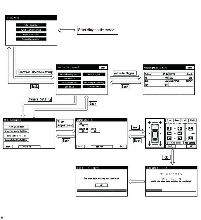
DIAGNOSIS SCREEN TRANSITION (STEERING ANGLE SETTING)
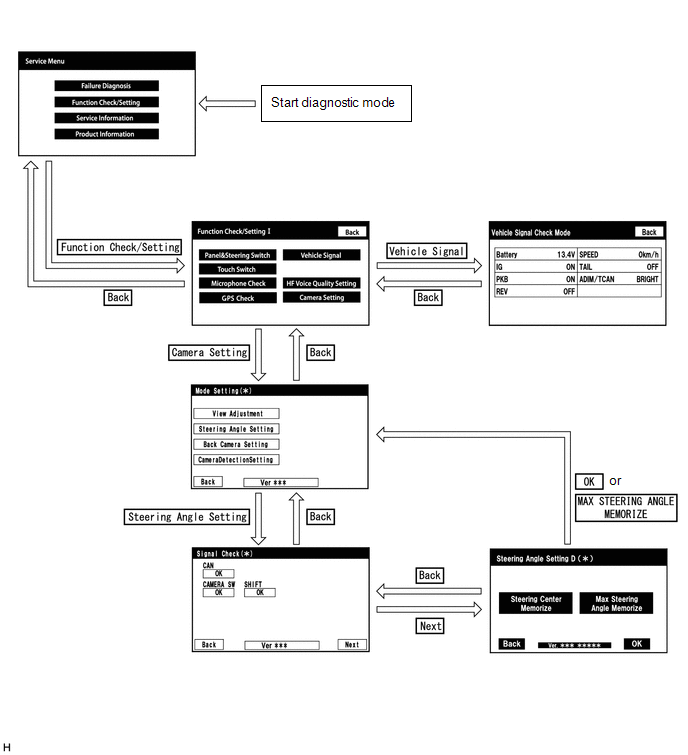
DIAGNOSIS SCREEN TRANSITION (BACK CAMERA SETTING)
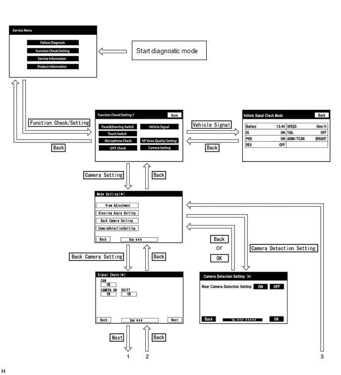
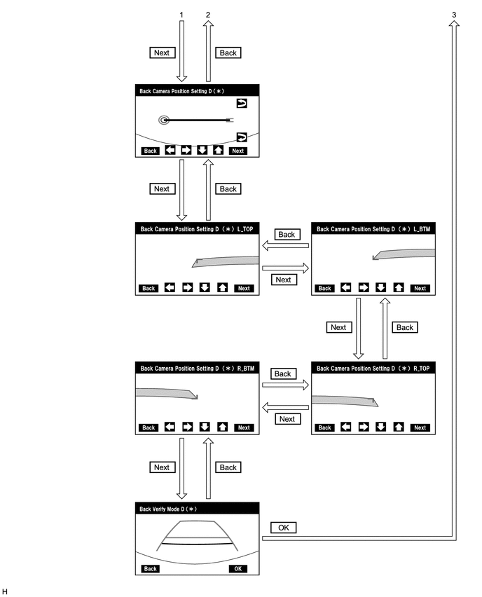
DIAGNOSTIC MODE
(a) Diagnostic mode
- Click here

(b) Failure diagnosis
- Click here

(c) System check (check using system check mode screen)
- Click here

(d) Finish diagnostic mode.
- Click here

SIGNAL CHECK (parking assist ECU input signal)
(a) Start diagnostic mode.
- Click here

(1) Select "Function Check/Setting" on the "Service Menu" screen to display the "Function Check/Setting I" screen.
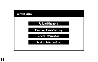
(2) Select "Camera Setting" on the "Function Check/Setting I" screen.
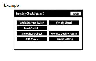
HINT:
After
"Camera Setting" is selected, the screen transitions differ depending
on whether initialization of the parking assist ECU was performed after
parking assist ECU replacement.
|
Parking Assist ECU Initialization |
Screen Transition |
|
Not performed | "Signal Check" screen |
|
Performed | "Mode Setting" screen |
(3) When the screen changes to the "Mode Setting" screen, select "View Adjustment" to display the "Signal Check" screen.
HINT:
To select a grayed out item, select and hold the item for 2 seconds or more.
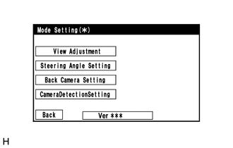
(b) Signal check
(1)
On the "Signal Check" screen, it is possible to inspect the state of
signals sent to the parking assist ECU and check the settings.
|
Item | Inspection Detail |
Note |
| CAN |
Speed signal input |
When "CHK" (red) is displayed, selecting "Next" will not change to the next screen. |
|
SHIFT | Shift position signal input |
|
CAMERA SW | Panoramic view monitor switch signal input |
HINT:
- When "CHK" (red) is displayed, perform inspections based on the result of the following inspections.
- If performing the adjustment after proceeding to the next screen, check
that all items display "OK" (blue) before selecting "Next".
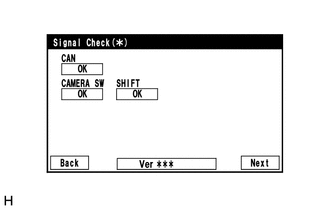
(c) CAN inspection
HINT:
If "CHK" (red) is displayed for "CAN", check for DTCs and perform troubleshooting based on the output DTCs.
Click here 
(d) SHIFT inspection
HINT:
If "CHK" (red) is displayed for "SHIFT", check for DTCs and perform troubleshooting based on the output DTCs.
Click here 
(e) CAMERA SW inspection
(1) Check that "OK" (blue) is displayed for "CAMERA SW" and select "OK".
HINT:
If
"CHK" (red) remains displayed or the "CAMERA SW" inspection result is
not normal, perform troubleshooting according to the Problem Symptoms
Table ("CHK" message(s) are displayed on the "Signal Check" screen).
Click here

(f) Finish diagnostic mode.
- Click here

CAMERA DETECTION SETTING
HINT:
Illustrations
may differ from the actual vehicle screen depending on the device
settings and options. Therefore, some detailed areas may not be shown
exactly the same as on the actual vehicle screen.
(a) Start diagnostic mode.
- Click here

(1) Select "Function Check/Setting" on the "Service Menu" screen to display the "Function Check/Setting I" screen.

(2) Select "Camera Setting" on the "Function Check/Setting I" screen.

(b) Camera Detection Setting
(1) Select "Camera Detection Setting" on the "Mode Setting " screen.

(2) Select ON or OFF on the "Camera Detection Setting" screen as necessary.
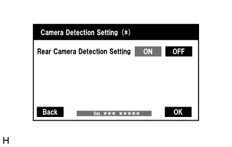
HINT:
After selecting ON or OFF, return to the "Mode Setting" screen by selecting "OK" or "Back".
(c) Finish diagnostic mode.
- Click here

CALIBRATION WHEN SERVICING VEHICLE
NOTICE:
Depending
on the parts that are replaced or operations that are performed during
vehicle inspection or maintenance, calibration of other systems as well
as the panoramic view monitor system may be needed.
Click here

Diagnostic Trouble Code Chart
DIAGNOSTIC TROUBLE CODE CHART
Panoramic View Monitor System |
DTC No. | Detection Item |
DTC Detection Condition | DTC Output from |
Link |
| C1611 |
ECU Malfunction | When any of the following conditions is met:
- EEPROM status (Initial read) malfunction
- CPU communication malfunction
- Video output malfunction
| Television camera assembly |
 |
|
C1614 | ECU Malfunction |
- Power source malfunction
- Main CPU start malfunction
- Main CPU reset detected
- Main CPU regular monitoring malfunction
- CAN CPU start malfunction
- System standby malfunction
- Main EEPROM malfunction
- Sub EEPROM malfunction
- ECU internal display line malfunction
| Parking assist ECU |
 |
|
C1621 | Back Camera Power Supply Failure |
Television camera assembly power supply failure |
Television camera assembly |
 |
|
C1622 | Open or Short Circuit in Back Camera Signal |
Open or short in the rear television camera signal circuit |
Parking assist ECU |
 |
|
C1625 | Open or Short in Steering Angle Sensor +B |
Open or short in steering angle sensor +B |
Parking assist ECU |
 |
|
C1625 | Open or Short in Steering Angle Sensor +B |
Open or short in steering angle sensor +B |
Television camera assembly |
 |
|
C1626 | Steering Angle Sensor Failure |
A fail flag is transmitted from the steering angle sensor |
Parking assist ECU |
 |
|
C1626 | Steering Angle Sensor Failure |
A fail flag is transmitted from the steering angle sensor |
Television camera assembly |
 |
|
C164D | Wheel Speed Sensor Malfunction |
Wheel speed sensor malfunction |
Parking assist ECU |
 |
|
C164D | Wheel Speed Sensor Malfunction |
Wheel speed sensor malfunction |
Television camera assembly |
 |
|
C1681 | Front Camera Feedback Malfunction |
Front television camera power supply failure |
Parking assist ECU |
 |
|
C1682 | Front Camera Current Malfunction |
Open or short in the front television camera signal circuit |
Parking assist ECU |
 |
|
C1683 | Side Camera Feedback Malfunction |
Side camera feedback malfunction |
Parking assist ECU |
 |
|
C1684 | Side Camera Current Malfunction |
Side camera current malfunction |
Parking assist ECU |
 |
|
C1686 | Driver Side Camera Video Sync Signal Malfunction |
Side camera feedback malfunction |
Parking assist ECU |
 |
|
C1687 | Over Current Detected in Driver Side Camera |
Side camera current malfunction |
Parking assist ECU |
 |
|
C168D | Vehicle Information Unmatched |
Vehicle information unmatched |
Parking assist ECU |
 |
|
C168D | Vehicle Information Unmatched |
Vehicle information unmatched |
Television camera assembly |
 |
|
C1691 | Back Camera Initialization Incomplete |
Back
camera initial setting has not been memorized (television camera
assembly optical axis adjustment (back camera position setting) is
incomplete) | Relevision camera assembly |
 |
|
C1694 | Steering Angle Initialization Incomplete |
Maximum steering angle has not been memorized |
Parking assist ECU |
 |
|
C1694 | Steering Angle Initialization Incomplete |
Maximum steering angle has not been memorized |
Television camera assembly |
 |
|
C1697 | Camera Position Adjustment Incomplete |
Camera initial setting has not been memorized |
Parking assist ECU |
 |
|
C2A5C | BSM Buzzer Sound Request Signal Malfunction |
An invalid communication signal is received from the blind spot monitor sensor RH |
Television camera assembly |
 |
|
C2A5D | BSM Buzzer Malfunction |
The RCTA buzzer circuit is abnormal. |
Television camera assembly |
 |
|
C2A63 | Back Camera Internal Circuit |
A signal indicating a malfunction in the television camera assembly is detected. |
Parking assist ECU |
 |
|
C2A6A | Back Camera Response Malfunction |
Abnormal response from the television camera assembly |
Parking assist ECU |
 |
|
U0073 | Control Module Communication Bus Off |
Control module communication bus off |
Parking assist ECU |
 |
|
U0100 | Lost Communication with ECM / PCM "A" |
Lost Communication with hybrid vehicle control ECU assembly |
Parking assist ECU |
 |
|
U0100 | Lost Communication with ECM / PCM "A" |
Lost Communication with hybrid vehicle control ECU assembly |
Television camera assembly |
 |
|
U0126 | Lost Communication with Steering Angle Sensor Module |
Lost communication with steering sensor |
Parking assist ECU |
 |
|
U0126 | Lost Communication with Steering Angle Sensor Module |
Lost communication with steering sensor |
Television camera assembly |
 |
|
U0129 | Lost Communication with Brake System Control Module |
Lost communication with skid control ECU |
Parking assist ECU |
 |
|
U0129 | Lost Communication with Brake System Control Module |
Lost communication with skid control ECU |
Television camera assembly |
 |
|
U0140 | Lost Communication with Body Control Module |
Lost communication with main body ECU (multiplex network body ECU) |
Parking assist ECU |
 |
|
U0140 | Lost Communication with Body Control Module |
Lost communication with main body ECU (multiplex network body ECU) |
Television camera assembly |
 |
|
U0163 | Lost Communication with Navigation Control Module |
Lost communication with radio and display receiver assembly |
Parking assist ECU |
 |
|
U0163 | Lost Communication with Navigation Control Module |
Lost communication with radio and display receiver assembly |
Television camera assembly |
 |
|
U0233 | Lost Communication with Blind Spot Monitor Master Module |
Lost communication with blind spot monitor sensor RH |
Parking assist ECU |
 |
|
U0233 | Lost Communication with Blind Spot Monitor Master Module |
Lost communication with blind spot monitor sensor RH |
Television camera assembly |
 |
|
U023B | Lost Communication with Panoramic View Monitor Control Module |
Lost Communication with parking assist ECU |
Television camera assembly |
 |
|
U0265 | Lost Communication with Image Processing Sensor A |
Lost Communication with television camera assembly |
Parking assist ECU |
 |
|
U1000 | CAN Communication Failure (Message Registry) |
ECU malfunction | Parking assist ECU |
 |
|
U1000 | CAN Communication Failure (Message Registry) |
ECU malfunction | Television camera assembly |
 |
|
U1110 | Lost Communication with Clearance Warning ECU |
Lost communication with clearance warning ECU assembly |
Parking assist ECU |
 |
Dtc Check / Clear
DTC CHECK / CLEAR
CHECK DTC
(a) Connect the Techstream to the DLC3.
(b) Turn the power switch on (READY).
(c) Turn the Techstream on.
(d) Enter the following menus: Chassis / Panoramic View Monitor / Trouble Codes.
(e) Check the details of the DTCs.
Chassis > Panoramic View Monitor > Trouble Codes
CLEAR DTC
(a) Connect the Techstream to the DLC3.
(b) Turn the power switch on (READY).
(c) Turn the Techstream on.
(d) Enter the following menus: Chassis / Panoramic View Monitor / Trouble Codes.
(e) According to the display on the Techstream, select the trouble code data display with the clear button.
Chassis > Panoramic View Monitor > Clear DTCsECU Power Source Circuit
DESCRIPTION
This circuit is
the power source circuit to operate the parking assist ECU. The parking
assist ECU controls the panoramic view monitor system.
WIRING DIAGRAM
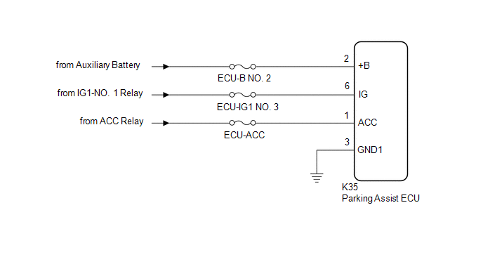
CAUTION / NOTICE / HINT
NOTICE:
Inspect the fuse for circuits related to this system before performing the following inspection procedure.
HINT:
If
the parking assist ECU does not operate due to a power source problem,
other system DTCs may be stored due to a CAN communication interruption.
PROCEDURE
| 1. |
CHECK HARNESS AND CONNECTOR (PARKING ASSIST ECU - BODY GROUND) |
(a) Disconnect the K35 parking assist ECU connector.
(b) Measure the resistance according to the value(s) in the table below.
Standard Resistance:
|
Tester Connection | Condition |
Specified Condition |
|
K35-3 (GND1) - Body ground |
Always | Below 1 Ω |
| NG |
 | REPAIR OR REPLACE HARNESS OR CONNECTOR |
|
OK |
 | |
| 2. |
CHECK HARNESS AND CONNECTOR (PARKING ASSIST ECU POWER SOURCE) |
(a) Disconnect the K35 parking assist ECU connector.
(b) Measure the voltage according to the value(s) in the table below.
Standard Voltage:
|
Tester Connection | Condition |
Specified Condition |
|
K35-2 (+B) - K35-3 (GND1) |
Power switch off | 11 to 14 V |
|
K35-1 (ACC) - K35-3 (GND1) |
Power switch on (ACC) |
11 to 14 V |
|
Power switch off | Below 1 V |
|
K35-6 (IG) - K35-3 (GND1) |
Power switch on (IG) |
11 to 14 V |
|
Power switch off | Below 1 V |
| OK |
 | PROCEED TO NEXT SUSPECTED AREA SHOWN IN PROBLEM SYMPTOMS TABLE |
| NG |
 | REPAIR OR REPLACE HARNESS OR CONNECTOR |
How To Proceed With Troubleshooting
CAUTION / NOTICE / HINT
HINT:
- Use the following procedure to troubleshoot the panoramic view monitor system.
- *: Use the Techstream.
PROCEDURE
|
1. | VEHICLE BROUGHT TO WORKSHOP |
|
NEXT |
 | |
| 2. |
INSPECT AUXILIARY BATTERY VOLTAGE |
(a) Measure the auxiliary battery voltage with power switch off.
Standard Voltage:
11 to 14 V
If the voltage is below 11 V, replace or recharge the auxiliary battery before proceeding.
|
NEXT |
 | |
| 3. |
CHECK NAVIGATION SYSTEM |
(a) Refer to Navigation System.
Click here 
OK:
Navigation system is normal.
| NG |
 | GO TO NAVIGATION SYSTEM |
|
OK |
 | |
| 4. |
CHECK COMMUNICATION FUNCTION OF CAN COMMUNICATION SYSTEM* |
(a) Use the Techstream to check if the CAN communication system is functioning normally.
Click here 
|
Result | Proceed to |
|
CAN DTCs are not output |
A |
| CAN DTCs are output |
B |
| B |
 | GO TO CAN COMMUNICATION SYSTEM |
|
A |
 | |
(a) Check for DTCs and note any codes that are output.
Chassis > Panoramic View Monitor > Trouble Codes
(b) Clear the DTCs.
Chassis > Panoramic View Monitor > Clear DTCs
(c) Recheck for DTCs. Try to reproduce the DTCs by simulating the original activity that the DTC suggests.
Chassis > Panoramic View Monitor > Trouble Codes
|
Result | Proceed to |
|
DTCs are not output | A |
|
DTCs are output | B |
| B |
 | GO TO DIAGNOSTIC TROUBLE CODE CHART |
|
A |
 | |
| 6. |
PROBLEM SYMPTOMS TABLE |
(a) Refer to the Problem Symptoms Table.
Click here 
|
Result | Proceed to |
|
Fault is not listed in Problem Symptoms Table |
A |
| Fault is listed in Problem Symptoms Table |
B |
| B |
 | GO TO STEP 8 |
|
A |
 | |
| 7. |
OVERALL ANALYSIS AND TROUBLESHOOTING* |
(a) Data List / Active Test
Click here 
(b) Terminals of ECU
Click here 
|
NEXT |
 | |
| 8. |
ADJUST, REPAIR OR REPLACE |
|
NEXT |
 | |
| NEXT |
 | END |
Image from Camera for Panoramic View Monitor is Abnormal
DESCRIPTION
The display signal from each camera is transmitted to the radio and display receiver assembly via the parking assist ECU.
WIRING DIAGRAM
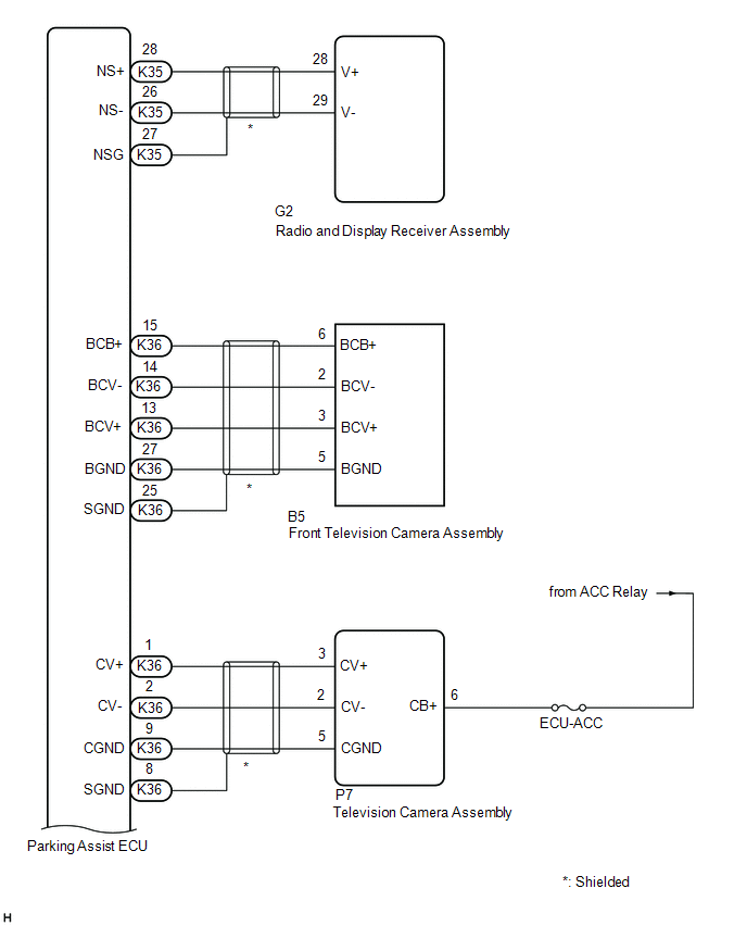
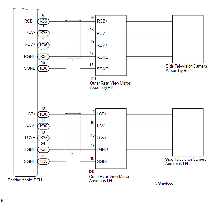
CAUTION / NOTICE / HINT
NOTICE:
- When "!" is displayed on the radio and display receiver assembly after
the cable is disconnected from the negative (-) auxiliary battery
terminal, correct the steering angle neutral point.
Click here 
- Depending on the parts that are replaced or operations that are
performed during vehicle inspection or maintenance, calibration of other
systems as well as the panoramic view monitor system may be needed.
Click here 
HINT:
Images may be unclear even in normal conditions if:
- Electrical devices are used in the cabin (noise may occur in the image).
- The camera lens is frosted over (the image immediately after turning the
power switch on (IG) may be blurred or darker than normal).
- The camera lens is dirty with snow, mud, etc.
- A strong beam of light, such as a sunbeam or headlight, hits the camera.
- It is too dark around the camera (at night, etc.).
- The ambient temperature around the camera is either too high or too low.
- The vehicle is tilted at a steep angle.
- The television camera assembly lens is scratched.
- The television camera assembly lens has drops of water on it or the humidity is high.
- When the camera is used under fluorescent lights, sodium lights, or
mercury lights, etc., the lights and the illuminated area may appear to
flicker.
PROCEDURE
|
1. | CHECK PANORAMIC VIEW MONITOR SYSTEM |
(a) Check if the same malfunction occurs when the panoramic view monitor screen is displayed.
|
Result | Proceed to |
|
Rear view screen is not displayed. |
A |
| Front view screen is not displayed. |
B |
| Left side monitor screen is not displayed. |
C |
| Right side monitor screen is not displayed. |
D |
| Panoramic view monitor screen is not displayed. |
E |
| B |
 | GO TO STEP 6 |
| C |
 | GO TO STEP 10 |
| D |
 | GO TO STEP 15 |
| E |
 | GO TO STEP 20 |
|
A |
 | |
| 2. |
CHECK HARNESS AND CONNECTOR (PARKING ASSIST ECU - TELEVISION CAMERA ASSEMBLY) |
Click here 
| NG |
 | REPAIR OR REPLACE HARNESS OR CONNECTOR |
|
OK |
 | |
| 3. |
CHECK HARNESS AND CONNECTOR (ACC POWER SUPPLY - GROUND) |
Click here 
| NG |
 | REPLACE PARKING ASSIST ECU |
|
OK |
 | |
| 4. |
CHECK PARKING ASSIST ECU (CV-, CGND) |
Click here

| NG |  |
REPLACE PARKING ASSIST ECU |
|
OK |
 | |
| 5. |
CHECK TELEVISION CAMERA ASSEMBLY (CV+, CGND) |
Click here 
| OK |
 | REPLACE PARKING ASSIST ECU |
| NG |
 | REPLACE TELEVISION CAMERA ASSEMBLY |
| 6. |
CHECK HARNESS AND CONNECTOR (PARKING ASSIST ECU - FRONT TELEVISION CAMERA ASSEMBLY) |
Click here 
| NG |
 | REPAIR OR REPLACE HARNESS OR CONNECTOR |
|
OK |
 | |
| 7. |
CHECK PARKING ASSIST ECU (BCV-, BGND) |
Click here 
| OK |
 | REPLACE PARKING ASSIST ECU |
|
NG |
 | |
| 8. |
CHECK PARKING ASSIST ECU (BCB+, BGND) |
Click here 
| NG |
 | REPLACE PARKING ASSIST ECU |
|
OK |
 | |
| 9. |
CHECK FRONT TELEVISION CAMERA ASSEMBLY (BCV+, BGND) |
Click here 
| OK |
 | REPLACE PARKING ASSIST ECU |
| NG |
 | REPLACE FRONT TELEVISION CAMERA ASSEMBLY |
| 10. |
CHECK HARNESS AND CONNECTOR (PARKING ASSIST ECU - OUTER REAR VIEW MIRROR ASSEMBLY LH) |
Click here 
| NG |
 | REPAIR OR REPLACE HARNESS OR CONNECTOR |
|
OK |
 | |
| 11. |
CHECK PARKING ASSIST ECU (LCV-, LGND) |
Click here 
| NG |
 | REPLACE PARKING ASSIST ECU |
|
OK |
 | |
| 12. |
CHECK PARKING ASSIST ECU (LCB+, LGND) |
Click here 
| NG |
 | REPLACE PARKING ASSIST ECU |
|
OK |
 | |
| 13. |
CHECK SIDE TELEVISION CAMERA ASSEMBLY LH (LCV+, LGND) |
Click here 
| OK |
 | REPLACE PARKING ASSIST ECU |
|
NG |
 | |
| 14. |
REPLACE SIDE TELEVISION CAMERA ASSEMBLY LH |
(a) Replace the side television camera assembly LH with a new or normally functioning one.
Click here 
(b) Check if the same malfunction reoccurs when the side monitor screen is displayed.
|
Result | Proceed to |
|
Malfunction does not reoccur (returns to normal) |
A |
| Malfunction reoccurs |
B |
| A |
 | END (SIDE TELEVISION CAMERA ASSEMBLY LH WAS DEFECTIVE) |
| B |
 | REPLACE OUTER REAR VIEW MIRROR ASSEMBLY LH |
| 15. |
CHECK HARNESS AND CONNECTOR (PARKING ASSIST ECU - OUTER REAR VIEW MIRROR ASSEMBLY RH) |
Click here 
| NG |
 | REPAIR OR REPLACE HARNESS OR CONNECTOR |
|
OK |
 | |
| 16. |
CHECK PARKING ASSIST ECU (RCV-, RGND) |
Click here 
| NG |
 | REPLACE PARKING ASSIST ECU |
|
OK |
 | |
| 17. |
CHECK PARKING ASSIST ECU (RCB+, RGND) |
Click here 
| NG |
 | REPLACE PARKING ASSIST ECU |
|
OK |
 | |
| 18. |
CHECK SIDE TELEVISION CAMERA ASSEMBLY RH (RCV+, RGND) |
Click here 
| OK |
 | REPLACE PARKING ASSIST ECU |
|
NG |
 | |
| 19. |
REPLACE SIDE TELEVISION CAMERA ASSEMBLY RH |
(a) Replace the side television camera assembly RH with a new or normally functioning one.
Click here 
(b) Check if the same malfunction reoccurs when the side monitor screen is displayed.
|
Result | Proceed to |
|
Malfunction does not reoccur (returns to normal) |
A |
| Malfunction reoccurs |
B |
| A |
 | END (SIDE TELEVISION CAMERA ASSEMBLY RH WAS DEFECTIVE) |
| B |
 | REPLACE OUTER REAR VIEW MIRROR ASSEMBLY RH |
| 20. |
CHECK HARNESS AND CONNECTOR (PARKING ASSIST ECU - RADIO AND DISPLAY RECEIVER ASSEMBLY) |
(a) Disconnect the K35 parking assist ECU connector.
(b) Disconnect the G2 radio and display receiver assembly connector.
(c) Measure the resistance according to the value(s) in the table below.
Standard Resistance:
|
Tester Connection | Condition |
Specified Condition |
|
K35-28 (NS+) - G2-28 (V+) |
Always | Below 1 Ω |
|
K35-26 (NS-) - G2-29 (V-) |
Always | Below 1 Ω |
|
K35-27 (NSG) - Body ground |
Always | Below 1 Ω |
|
K35-28 (NS+) or G2-28 (V+) - Body ground |
Always | 10 kΩ or higher |
|
K35-26 (NS-) or G2-29 (V-) - Body ground |
Always | 10 kΩ or higher |
| NG |
 | REPAIR OR REPLACE HARNESS OR CONNECTOR |
|
OK |
 | |
| 21. |
CHECK PARKING ASSIST ECU (NS-, NSG) |
(a) Disconnect the K35 parking assist ECU connector.
| (b) Measure the resistance according to the value(s) in the table below.
Standard Resistance: |
Tester Connection | Condition |
Specified Condition | |
27 (NSG) - Body ground |
Always | Below 1 Ω | |
26 (NS-) - Body ground |
Always | Below 1 Ω | |
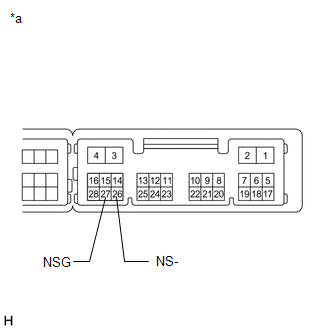 |
|
*a | Component without harness connected
(Parking Assist ECU) | | |
| NG |
 | REPLACE PARKING ASSIST ECU |
|
OK |
 | |
| 22. |
CHECK PARKING ASSIST ECU (NS+, NSG) |
(a) Remove the parking assist ECU with the connector still connected.
(b) Using an oscilloscope, check the waveform of the front television camera assembly.
HINT:
A
waterproof connector is used for the front television camera assembly.
Therefore, inspect the waveform at the parking assist ECU with the
connector connected.
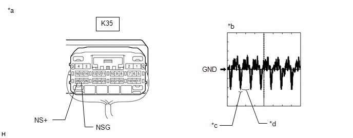
|
*a | Component with harness connected
(Parking Assist ECU) | *b |
Waveform 1 |
| *c |
Synchronization Signal |
*d | Video Waveform |
HINT:
The video waveform changes according to the image sent by the front television camera assembly.
Measurement Condition |
Item | Content |
|
Terminal No. (Symbol) |
K35-28 (NS+) - K35-27 (NSG) |
|
Tool Setting | 200 mV/DIV., 50 ÎĽsec./DIV. |
|
Condition | Power switch on (IG), Panoramic image being displayed |
OK:
Waveform is similar to that shown in the illustration.
| OK |
 | REPLACE RADIO AND DISPLAY RECEIVER ASSEMBLY |
| NG |
 | REPLACE PARKING ASSIST ECU |
Initialization
INITIALIZATION
INITIALIZE PANORAMIC VIEW MONITOR SYSTEM
(a)
When "!" is displayed on the radio and display receiver assembly,
correct the steering angle neutral point using the following method.
(1) Fully turn the steering wheel to the left and right on level ground.
NOTICE:
Memorizing
the steering angle neutral point must be carried out with the the power
switch on (READY). Apply the parking brake, depress the brake pedal,
check that the shift lever is in P, and ensure that the vehicle is not
moving.
HINT:
If the steering
angle neutral point cannot be memorized by fully turning the steering
wheel to the left and right, perform Steering Angle Setting in
Calibration.
Click here 
(b)
If the RCD OFF indicator is blinking and "RCD unavailable" is displayed
on the screen, perform the following procedure to set the steering
angle neutral point.
(1) Fully turn the steering wheel to the right and left on flat ground.
NOTICE:
Memorizing
the steering angle neutral point must be carried out with the power
switch on (READY). Apply the parking brake, depress the brake pedal,
check that the shift lever is in P, and ensure that the vehicle is not
moving.
HINT:
If estimated
course lines are not displayed on the image of the area behind the
vehicle with the steering wheel fully turned to the right or left,
perform "Steering Angle Setting in Calibration".
Click here

Parts Location
PARTS LOCATION
ILLUSTRATION
|
*1 | FRONT TELEVISION CAMERA ASSEMBLY |
*2 | TELEVISION CAMERA ASSEMBLY |
|
*3 | SIDE TELEVISION CAMERA ASSEMBLY LH |
*4 | SIDE TELEVISION CAMERA ASSEMBLY RH |
|
*5 | BRAKE BOOSTER WITH MASTER CYLINDER ASSEMBLY
- SKID CONTROL ECU | *6 |
HYBRID VEHICLE CONTROL ECU ASSEMBLY |
|
*7 | OUTER REAR VIEW MIRROR ASSEMBLY RH |
*8 | OUTER REAR VIEW MIRROR ASSEMBLY LH |
|
*9 | BLIND SPOT MONITOR SENSOR RH |
*10 | BLIND SPOT MONITOR SENSOR LH |
|
*11 | RCTA BUZZER (BLIND SPOT MONITOR BUZZER) |
- | - |
ILLUSTRATION
|
*1 | PANORAMIC VIEW MONITOR SWITCH |
*2 | STEERING SENSOR |
|
*3 | DLC3 |
*4 | RADIO AND DISPLAY RECEIVER ASSEMBLY |
|
*5 | PARKING ASSIST ECU |
*6 | CLEARANCE WARNING ECU ASSEMBLY |
|
*7 | MAIN BODY ECU (MULTIPLEX NETWORK BODY ECU) |
*8 | INSTRUMENT PANEL JUNCTION BLOCK ASSEMBLY
- ECU-IG1 NO. 3 FUSE - ECU-DCC NO. 1 FUSE - ECU-ACC FUSE
- ECU-B NO. 2 FUSE - ECU-IG1 NO. 2 FUSE - ACC Relay
- IG1-NO. 1 Relay - BKUP LP Relay |
Precaution
PRECAUTION
PRECAUTION FOR DISCONNECTING CABLE FROM NEGATIVE AUXILIARY BATTERY TERMINAL
NOTICE:
When
disconnecting the cable from the negative (-) auxiliary battery
terminal, initialize the following systems after the cable is
reconnected.
|
System Name | See Procedure |
|
Lane Departure Alert System (w/ Steering Control) |
 |
|
Intelligent Clearance Sonar System |
|
Parking Assist Monitor System |
|
Panoramic View Monitor System |
|
Pre-collision System |
| Lighting System (for HV Model with Cornering Light) |
POINTS TO NOTE WHEN SERVICING
(a) Pay attention to the following points when servicing.
(1)
When disconnecting the cable from the negative (-) auxiliary battery
terminal, "!" may appear on the radio and display receiver assembly. In
this case, restore the steering angle neutral point.
Click here

(2)
Depending on the parts that are replaced or operations that are
performed during vehicle inspection or maintenance, calibration of other
systems as well as the panoramic view monitor system may be needed.
Click here

HINT:
Each adjusted value for the calibration of the panoramic view monitor system will be stored in the parking assist ECU.
(3)
A clear image may not be displayed if there is foreign matter such as
water drops, snow or mud on the television camera lens. In such a case,
wash the lens with a large amount of water and then wipe it with a soft
wet cloth. Do not scrub the camera lens as scrubbing may scratch the
camera lens and affect the quality of the image.
PRECAUTIONS FOR PANORAMIC VIEW MONITOR SYSTEM
(a) In the following situations, the panoramic view monitor system may not operate correctly:
(1) When driving on icy, slippery or snowy roads
(2) When using tire chains or a spare tire
(3) When a door is not fully closed
(4) When driving on a slope or rough roads
(5) When using tires other than specified
(6) When the suspension of the vehicle has been modified
(b)
As the panoramic view monitor system generates the panoramic image by
combining images received from the front television camera assembly,
television camera assembly and side camera assemblies, the following
phenomenon may occur:
(1) A three dimensional object may appear tilted
(2) An object above the road surface may appear farther away than it actually is, or may not be displayed at all
(3) A tall object may look as if it is coming out from between 2 combined images
(4)
Depending on the brightness of the area surrounding each camera, there
may be a significant difference in the brightness of the images that are
used to generate the panoramic image.
(c) The image quality at the four corners of the panoramic image may be low as this is where the individual images are combined.
(d) Objects a certain height above the camera assemblies will not be displayed.
(e) Objects extremely close to the vehicle may not be displayed on the panoramic view monitor.
(f) The panoramic image may not be displayed correctly if a front door or the luggage compartment door is open.
(g)
The panoramic image may not be displayed correctly if the height or
inclination of the vehicle changes due to loading from passengers,
luggage, etc.
(h) As the size and shape of the
vehicle icon may differ from that of the actual vehicle, the position of
an object relative to the vehicle icon may appear different to its
actual position.
NOTES FOR EACH TELEVISION CAMERA ASSEMBLY
(a) Notes for each television camera assembly
(1) The panoramic view monitor system may not function properly if subjected to a severe blow by any hard object.
(2)
The cover part of the camera is made of resin. If any organic solvent,
degreaser, wax or glass coating contacts the cover, immediately wipe it
off and wash the cover with water or cracks may develop.
(3) Exposing the camera to a sudden temperature change may affect proper functioning of the camera.
(4)
A clear image may not be displayed if there is foreign matter such as
water drops, snow or mud on the television camera lens. In such a case,
wash the lens with a large amount of water and then wipe it with a soft
wet cloth. Do not scrub the camera lens as scrubbing may scratch the
camera lens and affect the quality of the image.
(5)
When washing the vehicle with a high-pressure washer, do not spray
water on the television camera assembly or surrounding area.
High-pressure water can damage the camera.
(b) Images may be unclear even in normal conditions if:
(1) The outer mirror switch assembly is operated (noise may occur in the image).
(2) Electrical devices are used in the cabin (noise may occur in the image).
(3) Accessories that generate radio waves have been installed (noise may occur in the image).
(4)
The camera lens is frosted over (the image immediately after turning
the power switch on (IG) may be blurred or darker than normal).
(5) The camera lens is dirty with snow, mud, etc.
(6) The lens of a camera is covered with foreign matter.
(7) A strong beam of light, such as a sunbeam or headlight, hits the camera.
(8) It is too dark around the camera (at night, etc.).
(9) The ambient temperature around the camera is either too high or too low.
(10) The vehicle is tilted at a steep angle.
(11) The area around the vehicle is not sufficiently bright.
(12) The television camera assembly lens is scratched.
(13) The television camera assembly lens has drops of water on it or the humidity is high.
(14)
When the camera is used under fluorescent lights, sodium lights or
mercury lights, etc., the lights and the illuminated area may appear to
flicker.
NOTICE OF REAR CAMERA DETECTION FUNCTION
(a) The rear camera detection function may not be able to detect some pedestrians correctly, such as the following
(1) Pedestrians who are squatting
(2) Pedestrians who are lying down
(3) Pedestrians who are running
(4) Pedestrians who suddenly enter the detection area
(5) Pedestrians riding a bicycle, skateboard, or other light vehicle
(6) Pedestrians wearing unusual clothing, such as a costume
(7) Pedestrians whose body is partially hidden by a cart or other object
(8) Pedestrians who are obscured by darkness, such as at night
(b) The rear camera detection function may not be able to detect pedestrians correctly in the following conditions:
(1) When visibility is poor due to rain, snow, fog, nighttime, etc.
(2) When foreign matter such as water or snow is on the television camera assembly
(3) When a bright light such as the sun or headlights of another vehicle shines directly into the television camera assembly
(4) When the surrounding brightness changes suddenly such as at the entrance/exit of a garage or underground parking lot
(c) The rear camera detection function may accidentally detect the following objects as pedestrians:
(1) A three dimensional object such as a pole, traffic cone, fence or parked vehicle
(2) A moving vehicle such as a car or motorcycle
(3) A moving object such as a flag, smoke, raindrops, snow or puddle
(4)
A pattern on the road surface such as white lines, pedestrian
crossings, cobblestones, tram rails, traces of repair, fallen leaves or
gravel
(5) A metal cover (grating) or drainage ditch
(6) The edge of the road, or a bump in the road
(7) A reflection in a puddle or on a wet road surface
(8) A shadow on the road
(d) The rear camera detection function may accidentally detect an object in the following conditions:
(1) When driving over a joint in the road surface
(2) When the vehicle is significantly tilted, such as when carrying a heavy load or during sudden braking
(3) When the vehicle is on varying gradients
(4) When the vehicle is equipped with lowered suspension or tires with a diameter different to that of the original
(5) When the height of the vehicle has drastically changed (the nose is tilted up or down)
(6) When an electronic component such as a fog light is installed near the television camera assembly
(7) When a bumper protector such as an additional trim strip is installed to the rear bumper assembly
(8) When the television camera assembly is misaligned
(9) When a towing eyelet is installed to the rear bumper assembly
(10) When foreign matter such as water or snow is on the television camera assembly
(11) When water is flowing over the television camera assembly
(12) When there is a flashing light in the detection area, such as the hazard lights of another vehicle.
(e) The warning of the rear camera detection function may be difficult to notice in the following situations:
(1) When the multi-display screen is not operating correctly due to extremely high or low temperatures in the cabin.
(2)
When loud noises make it difficult to hear the RCTA buzzer (blind spot
monitor buzzer) such as when the audio system volume is high.
Problem Symptoms Table
PROBLEM SYMPTOMS TABLE
NOTICE:
- The following inspection procedure of the panoramic view monitor system
is described on the assumption that the navigation system is normal. If
the navigation system has any malfunction, first proceed with
troubleshooting of the navigation system.
- Depending on the parts that are replaced or operations that are
performed during vehicle inspection or maintenance, calibration of other
systems as well as the panoramic view monitor system may be needed.
HINT:
Use the
table below to help determine the cause of problem symptoms. If multiple
suspected areas are listed, the potential causes of the symptoms are
listed in order of probability in the "Suspected Area" column of the
table. Check each symptom by checking the suspected areas in the order
they are listed. Replace parts as necessary.
General |
Symptom | Suspected Area |
Link |
|
Display does not switch when the panoramic view monitor switch is pressed. |
Refer to "Panoramic View Screen Description" in system description |
 |
|
Proceed to "ECU Power Source Circuit" |
 |
|
Diagnostic mode - Signal connection check (CAMERA SW check) |
 |
|
Replace parking assist ECU |
 |
|
Display
does not switch to the panoramic view and rear view screen, wide rear
view screen, or narrow rear view screen when the shift lever is in R. |
Diagnostic mode - Signal connection check (SHIFT check) |
 |
|
Replace parking assist ECU |
 |
|
Image
not displayed on the panoramic view and rear view screen, wide rear
view screen or narrow rear view screen when the shift lever is in R. |
Proceed to "Image from Camera for Panoramic View Monitor is Abnormal" |
 |
|
Display does not switch to the see through view screen or moving view screen when the panoramic view monitor switch is pressed. |
Refer to "Panoramic View Screen Description" in system description |
 |
|
Diagnostic mode - Signal connection check (CAN check) |
 |
|
Diagnostic mode - Signal connection check (CAMERA SW check) |
 |
|
Replace parking assist ECU |
 |
|
Image not displayed on the see through view screen or moving view screen when the panoramic view monitor switch is pressed. |
Proceed to "Image from Camera for Panoramic View Monitor is Abnormal" |
 |
|
Display
does not switch to the panoramic view and wide front view screen or the
two-side view screen when the panoramic view monitor switch is pressed. |
Proceed to Description "Panoramic View Monitor Screen Display Conditions" |
 |
|
Diagnostic mode - Signal connection check (CAN check) |
 |
|
Diagnostic mode - Signal connection check (CAMERA SW check) |
 |
|
Replace parking assist ECU |
 |
|
Image
not displayed on the panoramic view and wide front view screen or the
two-side view screen when the panoramic view monitor switch is pressed. |
Proceed to "Image from Camera for Panoramic View Monitor is Abnormal" |
 |
Display Malfunction |
Symptom | Suspected Area |
Link |
| Objects not displayed correctly on the panoramic view monitor screen (color, distorted image). |
Proceed to "Image from Camera for Panoramic View Monitor is Abnormal" |
 |
|
Distorted display on panoramic view screen. |
Camera view adjustment (calibration) |
 |
|
Replace parking assist ECU |
 |
|
Parking lines do not match at front and rear on panoramic view screen. |
Camera view adjustment (calibration) |
 |
|
Replace parking assist ECU |
 |
|
Partial black screen on panoramic view screen. |
Proceed to "Image from Camera for Panoramic View Monitor is Abnormal" |
 |
|
Camera view adjustment (calibration) |
 |
|
Replace parking assist ECU |
 |
|
Area displayed differs from the actual area. |
Ensure no door is opened |
- |
| Camera view adjustment (calibration) |
 |
|
Replace parking assist ECU |
 |
Switch Function |
Symptom | Suspected Area |
Link |
|
Panoramic view monitor switch night illumination does not illuminate. |
Inspect panoramic view monitor switch |
 |
|
Harness or connector |
- |
|
The touch function of the screen does not operate for any system. |
Proceed to "Touch Panel Switch does not Function" |
 |
|
Replace parking assist ECU |
 |
|
Radio and display receiver assembly |
 |
|
The touch function of the screen does not operate for the panoramic view monitor system. |
Replace parking assist ECU |
 |
|
Radio and display receiver assembly |
 |
Panoramic View Monitor System Function |
Symptom | Suspected Area |
Link |
| When
the vehicle speed increases in the automatic display mode, the
panoramic view and wide front view screen or the two-side view screen
remains displayed, without switching to the navigation screen. |
Replace parking assist ECU |
 |
|
The screen display timer function does not operate if the manual display mode is selected. |
Refer to "Panoramic View Screen Description" in system description |
 |
|
Replace parking assist ECU |
 |
|
The estimated course lines do not match the vehicle width extension lines when the steering wheel points straight ahead. |
Check the steering wheel installation angle |
 |
|
Adjust steering angle |
 |
|
Camera view adjustment (calibration) |
 |
|
Replace parking assist ECU |
 |
|
Estimated course lines stop moving before the steering wheel is turned fully left. |
Steering angle setting (calibrate stored maximum steering angle) |
 |
|
"!" is displayed and estimated course lines are not displayed. |
Check if the luggage compartment door is not open |
- |
| Replace parking assist ECU |
 |
|
Replace radio and display receiver assembly |
 |
|
Estimated course lines are not displayed. |
Check the panoramic view monitor screen display mode settings (Check if the estimated course lines display is set to off) |
 |
|
Replace parking assist ECU |
 |
|
"!" is displayed. | Store the steering angle sensor steering neutral point |
 |
|
"!" remains displayed after the steering neutral point is stored. |
Adjust steering angle |
 |
|
Replace steering sensor |
 |
|
Replace parking assist ECU |
 |
|
"!" is displayed and all the buttons on the screen are grayed out. |
Camera view adjustment (calibration) |
 |
|
Adjust steering angle |
 |
|
Refer to Navigation System |
 |
|
"!"
is displayed and all the buttons on the screen are grayed out even
after parking assist ECU initialization has been completed. |
Replace parking assist ECU |
 |
|
Refer to Navigation System |
 |
|
Guide lines and buttons are not displayed on the panoramic view and rear view screen display screen. |
Check if the luggage compartment door is not open |
- |
| Check
if the luggage compartment light turns on and off normally (If not,
refer to Lighting System (Interior) - Problem Symptoms Table) |
 |
|
Replace parking assist ECU |
 |
|
"CHK" is displayed for an item on the Vehicle Signal Check screen. |
Diagnostic mode - Signal connection check |
 |
|
Blind spots in image. | Ensure no door is opened |
- |
| Camera view adjustment (calibration) |
 |
|
Camera boundary lines are poorly connected. |
Camera view adjustment (calibration) |
 |
|
Estimated course lines are displaced. |
Camera view adjustment (calibration) |
 |
|
Adjust steering angle |
 |
|
All buttons on the panoramic view monitor are continuously grayed out |
Refer to Navigation System |
 |
Rear Camera Detection Function Malfunction |
Symptom | Suspected Area |
Link |
|
When the parking assist monitor screen is displayed, "RCD unavailable" is displayed. |
Correct the steering angle neutral point (Initialization) |
 |
|
Blind spot monitor system |
 |
|
Television camera assembly |
 |
|
When the parking assist monitor screen is displayed, "RCD malfunction. Visit your dealer" is displayed. |
Television camera assembly |
 |
|
The indicator does not respond when the mute switch is pushed. |
Proceed to "Touch Panel Switch does not Function" |
 |
|
Television camera assembly |
 |
|
Replace parking assist ECU |
 |
|
Radio and display receiver assembly |
 |
|
When there is a pedestrian in the detection area, no pedestrian is detected. |
Refer to "Notes for Rear Camera Detection Function" in precaution |
 |
|
Perform calibration |
 |
|
Television camera assembly |
 |
|
When there is no pedestrian in the detection area, a pedestrian is detected. |
Refer to "Notes for Rear Camera Detection Function" in precaution |
 |
|
Perform calibration |
 |
|
Television camera assembly |
 |
|
A pedestrian who is in the absolute no detection area* is detected. |
Perform calibration |
 |
|
Television camera assembly |
 |
|
A pedestrian is only detected when they are in the absolute detection area*. |
Perform calibration |
 |
|
Television camera assembly |
 |
- *: Refer to "Operation Explanation" in system description
Click here 
System Description
SYSTEM DESCRIPTION
GENERAL
(a)
This system has front, passenger side, driver side and television
camera assemblies mounted around the vehicle to display around the
vehicle on the radio and display receiver assembly. The multi-display
also shows a composite view consisting of the area behind the vehicle
and parking guidelines to assist the driver in parking the vehicle by
monitoring the area around the vehicle.
When the
rear camera detection function of the television camera assembly detects
a pedestrian within the detection area when reversing, a buzzer sounds
and an icon is displayed on the multi-display to warn the driver.
(b) This system consists of the following components:
(1) Parking assist ECU
(2) Panoramic view monitor switch
(3) Television camera assembly
(4) Front television camera assembly
(5) Side television camera assembly LH
(6) Side television camera assembly RH
(7) Radio and display receiver assembly
(8) Network gateway ECU
(9) Steering Sensor
(10) Skid control ECU
(11) Main body ECU (multiplex network body ECU)
(12) Clearance warning ECU assembly
(13) Hybrid Vehicle Control ECU Assembly
(14) Blind spot monitor sensor
(15) RCTA buzzer (blind spot monitor buzzer)
(16) BKUP LP relay
(c)
This system is equipped with a self-diagnosis system, which is operated
from a designated window that appears on the multi-display, just as in
the navigation system.
FUNCTION OF COMPONENTS
(a) The parking assist ECU controls the system by using information from the following components.
|
Item | Function |
|
Television Camera Assembly |
- Generates a video feed showing the rear side of the vehicle and transmits the video to the parking assist ECU
- Transmits a camera detection buzzer request signal to the blind spot monitor sensor via CAN communication.
|
| Front Television Camera Assembly |
Generates a video feed showing the front side of the vehicle and transmits the video to the parking assist ECU |
|
Side Television Camera Assembly LH | Generates a video feed showing the left side of the vehicle and transmits the video to the parking assist ECU |
|
Side Television Camera Assembly RH | Generates a video feed showing the right side of the vehicle and transmits the video to the parking assist ECU |
|
Parking Assist ECU |
- Turns the panoramic view monitor system ON and OFF according to the
display conditions, based on the received panoramic view monitor switch
signals, shift position signals, and vehicle speed signals
- Transmits the display request signals for the panoramic view and wide
front view screen, two-side view screen, panoramic view and rear view
screen, wide rear view screen, narrow rear view screen, see through view
screen, or moving view screen to the radio and display receiver
assembly according to the display conditions, based on the received
panoramic view monitor switch signals, shift position signals, and
vehicle speed signals
- Displays the composite image of the surrounding area images taken by
each camera and the image calculated from vehicle status information
such as the steering angle signals on the radio and display receiver
assembly screen
- Renders each configuration page in the diagnosis window and outputs the screen to the radio and display receiver assembly
- Stops displaying the buttons and guidelines on the panoramic view and
rear view monitor screen when the screen is being displayed and a
luggage compartment door open status signal is received
- Stores each configuration setting from the diagnosis window
- Receives the reverse signal from the BKUP LP relay.
|
| Panoramic View Monitor Switch |
Transmits switch operation signals to the parking assist ECU |
|
Radio and display receiver assembly |
- Receives the video signals from the Parking Assist ECU, and displays them on the multi-display
- Allows operations when the panoramic view monitor screen or diagnosis screen is displayed
|
| Steering Sensor |
Transmits the steering angle signals and sensor status signals to the parking assist ECU via the CAN communication |
|
Skid Control ECU | Transmits
the vehicle speed signals, drive type signals, and system status
signals to the parking assist ECU via the CAN communication |
|
Hybrid Vehicle Control ECU Assembly |
- Transmits the engine model signals, and system status signals to the parking assist ECU via the CAN communication
- Transmits the shift position signals to the parking assist ECU via the CAN communication
|
| Main Body ECU (Multiplex Network Body ECU) |
Transmits the luggage compartment door courtesy light switch signal to the parking assist ECU via the CAN communication |
|
Clearance Warning ECU Assembly | Transmits information from each sonar via the CAN communication |
|
Blind Spot Monitor Sensor | Transmits the RCTA information signal via CAN communication |
|
RCTA Buzzer (Blind Spot Monitor Buzzer) |
Sounds based on a signal from the blind spot monitor sensor. |
|
BKUP LP Relay | Transmits the reverse signal to the parking assist ECU |
PANORAMIC VIEW SCREEN DISPLAY
(a) See-through view screen
(1) The entire area surrounding the vehicle is displayed.
|
*a | Vehicle interior view |
*b | Upper view |
(b) Moving view screen
(1) The entire area surrounding the vehicle is displayed.
|
*a | Slant upper view | *b |
Upper view |
(c) Panoramic view and wide front view screen
|
*a | Estimated course line display mode |
*b | Distance guide line display mode |
Panoramic View and Wide Front View Screen Description |
Signal | Name |
Color | Panoramic View and Wide Front View Screen |
|
Estimated course line display mode | Distance guide line display mode |
|
(1) | Front distance guide line |
Blue | Displayed |
Displayed |
|
(2) | Front forward estimated course line |
Yellow | Displayed |
Not displayed |
(d) Two-side view screen description
 Two-side View Screen Description
 |
Signal | Name |
Color |
| (1) |
Front distance guide line |
Red/Black |
|
(2) | Front wheel ground contact line |
Blue |
| (3) |
Vehicle width parallel line |
Blue |
(e) Panoramic view and rear view screen
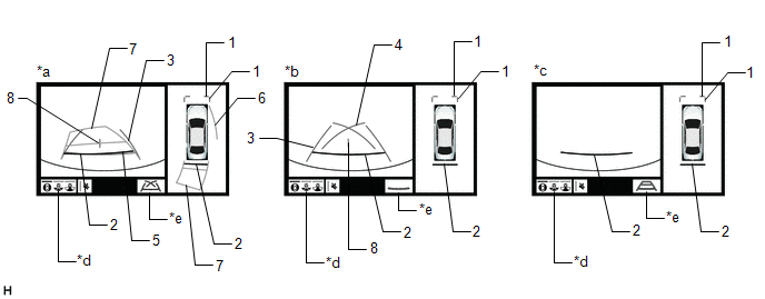
|
*a | Estimated course line display mode |
*b | Parking guide line display mode |
|
*c | Distance guide line display mode |
*d | Display mode switching button |
|
*e | Guide line display mode switching button |
- | - |
HINT:
The screen changes to the wide rear view screen when the display mode switch button or rear view screen is selected.
Panoramic View and Rear View Screen Description |
Signal | Name |
Color | Panoramic View and Rear View Screen |
|
Estimated course line display mode |
Parking guide line display mode |
Distance guide line display mode |
|
(1) | Front distance guide line |
Blue | Displayed |
Displayed | Displayed |
|
(2) | Rear distance guide line |
Red/Black | Displayed |
Displayed | Displayed |
|
(3) | Rear vehicle width extension line |
Blue | Displayed |
Displayed | Not displayed |
|
(4) | Parking guide line |
Blue | Not displayed |
Displayed | Not displayed |
|
(5) | Rear distance guide line |
Blue | Displayed |
Not displayed | Not displayed |
|
(6) | Side estimated course line |
Yellow | Displayed |
Not displayed | Not displayed |
|
(7) | Rear estimated course line |
Yellow | Displayed |
Not displayed | Not displayed |
|
(8) | Vehicle center line |
Blue | Displayed |
Displayed | Not displayed |
(f) Wide rear view screen
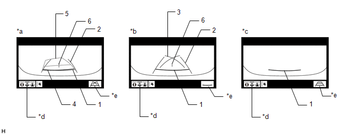
|
*a | Estimated course line display mode |
*b | Parking guide line display mode |
|
*c | Distance guide line display mode |
*d | Display mode switching button |
|
*e | Guide line display mode switching button |
- | - |
HINT:
The screen changes to the narrow rear view screen when the display mode switch button or rear view screen is selected.
Wide Rear View Screen Description |
Signal | Name |
Color | Rear View Screen |
|
Estimated course line display mode |
Parking guide line display mode |
Distance guide line display mode |
|
(1) | Rear distance guide line |
Red/Black | Displayed |
Displayed | Displayed |
|
(2) | Rear vehicle width extension line |
Blue | Displayed |
Displayed | Not displayed |
|
(3) | Parking guide line |
Blue | Not displayed |
Displayed | Not displayed |
|
(4) | Rear distance guide line |
Blue | Displayed |
Not displayed | Not displayed |
|
(5) | Rear estimated course line |
Yellow | Displayed |
Not displayed | Not displayed |
|
(6) | Vehicle center line |
Blue | Displayed |
Displayed | Not displayed |
(g) Narrow Rear view screen
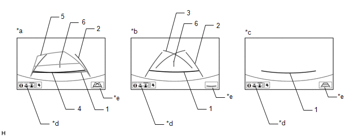
|
*a | Estimated course line display mode |
*b | Parking guide line display mode |
|
*c | Distance guide line display mode |
*d | Display mode switching button |
|
*e | Guide line display mode switching button |
- | - |
HINT:
The
screen changes to the panoramic view and rear view screen when the
display mode switch button or rear view screen is selected.
Narrow Rear View Screen Description |
Signal | Name |
Color | Rear View Screen |
|
Estimated course line display mode |
Parking guide line display mode |
Distance guide line display mode |
|
(1) | Rear distance guide line |
Red/Black | Displayed |
Displayed | Displayed |
|
(2) | Rear vehicle width extension line |
Blue | Displayed |
Displayed | Not displayed |
|
(3) | Parking guide line |
Blue | Not displayed |
Displayed | Not displayed |
|
(4) | Rear distance guide line |
Blue | Displayed |
Not displayed | Not displayed |
|
(5) | Rear estimated course line |
Yellow | Displayed |
Not displayed | Not displayed |
|
(6) | Vehicle center line |
Blue | Displayed |
Displayed | Not displayed |
(h) Rear camera detection function screen

|
*a | Narrow rear view screen |
*b | Wide rear view screen |
|
*c | Panoramic view and rear view screen |
*d | Display Mode Switching Button |
|
*e | Guide Line Display Mode Switching Button |
*f | Pedestrian Detection Icon |
|
*g | Mute Switch |
*h | RCD OFF Indicator (Displays Only when Rear Camera Detection is OFF)* |
- *: The setting can be changed on the diagnosis screen.
Click here 
PANORAMIC VIEW SCREEN DESCRIPTION
(a) Manual display mode
(1)
When the panoramic view monitor switch is pressed with the power switch
on (IG) or on (READY), the panoramic view monitor system switches to a
screen shown below according to the shift lever position
Screen Transition Chart (Manual Display Mode)
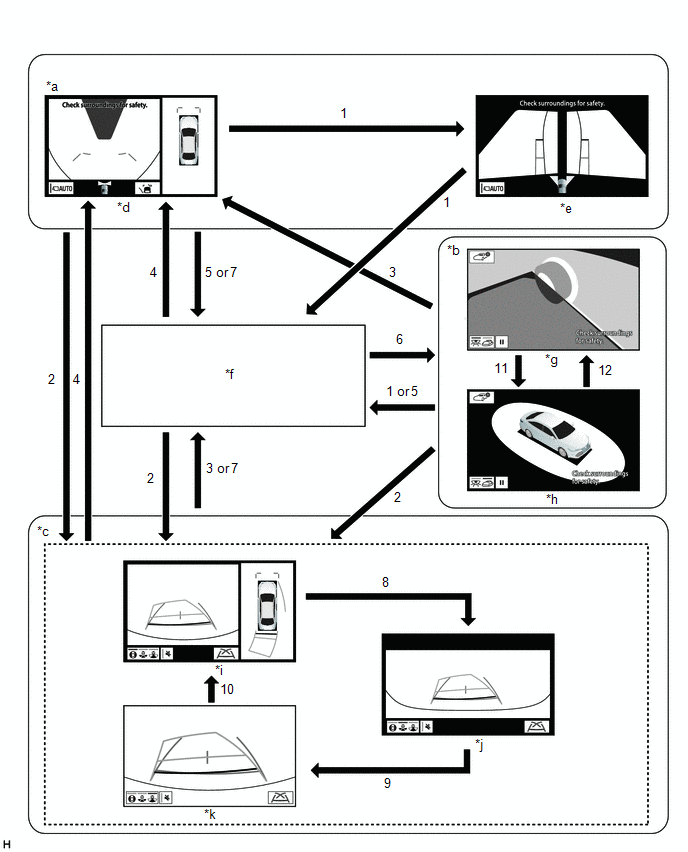
|
*a | Shift lever not in P or R |
*b | Shift lever in P and intelligent clearance sonar system on |
|
*c | Shift lever in R |
*d | Panoramic view and wide front view screen |
|
*e | Two-side view screen |
*f | Audio screen, etc. |
|
*g | See-through view screen |
*h | Moving view screen |
|
*i | Panoramic view and rear view screen |
*j | Wide rear view screen |
|
*k | Narrow rear view screen |
- | - |
Screen Transition Conditions (Manual Display Mode) |
No. | Screen Transition Conditions |
|
(1) | Panoramic view monitor switch is pressed |
|
(2) | Shift lever is moved to R |
|
(3) | Shift lever is moved to other than P or R |
|
(4) | Shift lever is moved to other than P or R and operation (1) is performed |
|
(5) | "HOME" switches, etc. on the radio and display receiver assembly are pressed |
|
(6) | Operation (1) is performed with the shift lever in P |
|
(7) | Shift lever is moved to P |
|
(8) | Display mode switching button or rear view screen is selected |
|
(9) | Display mode switching button or wide rear view screen is selected |
|
(10) | Display mode switching button or narrow rear view screen is selected |
|
(11) | Moving view switch button is selected |
|
(12) | See through view switch button is selected |
HINT:
If
the panoramic view monitor switch is pressed at a vehicle speed of
approximately 12 km/h (7.5 mph) or lower, the panoramic view monitor
system screen is displayed. If the vehicle speed exceeds approximately
12 km/h (7.5 mph), the display switches to the audio screen or
information settings screen.
(b) Screen transition chart (automatic display mode)
(1)
When the shift lever is not in P or R, in addition to switching screens
by pressing the panoramic view monitor switch, the automatic display
mode can be selected by pressing the automatic display mode switching
button.
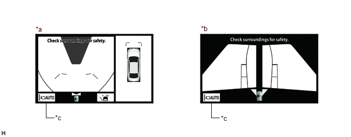
|
*a | Panoramic view and wide front view screen |
*b | Two-side view screen |
|
*c | Automatic display mode |
- | - |
|
Automatic Display Mode Switching Button (Indicator in Button) |
Screen Switching Mode |
|
ON (Illuminated) |
Automatic display mode |
|
OFF (Not illuminated) |
Manual display mode |
HINT:
- In the automatic display mode, press the panoramic view monitor switch
or panel switch to switch screens in the same way as the manual display
mode.
- When switching to the audio screen, etc. in the automatic display mode,
the display switches to the screen that was displayed last. However, the
display switches to the panoramic view and wide front view screen if
the shift lever is not in P or R after the power switch is turned from
off to on (IG).
(2) The automatic display mode automatically switches the display according to the vehicle status.
Screen Transition Chart (Automatic Display Mode)
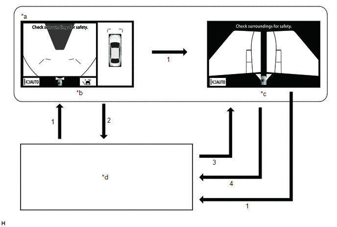
|
*a | Shift lever not in P or R |
*b | Panoramic view and wide front view screen |
|
*c | Two-side view screen |
*d | Audio screen, etc. |
Screen Transition Conditions (Automatic Display Mode) |
No. | Screen Transition Conditions |
|
*: The panoramic view and wide front view screen is the first screen displayed after the power switch was turned off.
|
| (1) |
Panoramic view monitor switch is pressed |
|
(2) | Current location switches, etc. on the radio and display receiver assembly are pressed |
|
(3) | Vehicle
speed changes from above approximately 10 km/h (6 mph) to approximately
10 km/h (6 mph) or lower. The screen that was last displayed is
displayed on the radio and display receiver assembly.* |
|
(4) | Vehicle speed changes from approximately 12 km/h (7 mph) or lower to above approximately 12 km/h (7 mph) |
(c) Panoramic View Zoom Function
(1)
When detail within the image on the panoramic view screen is too small
and difficult to see, the user can magnify the image by selecting one of
the 4 areas on the panoramic view screen.
Screen Transition
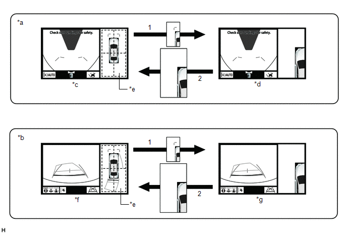
|
*a | Panoramic view and wide front view screen displayed while shift lever is not in P or R |
*b | Panoramic view and rear view screen displayed |
|
*c | Panoramic view and wide front view screen |
*d | Panoramic view and wide front view screen (Front left view magnified) |
|
*e | Panoramic view screen |
*f | Panoramic view and rear view screen |
|
*g | Panoramic view and rear view screen (Front left view magnified) |
- | - |
Screen Transition Conditions |
No. | Screen Transition Conditions |
|
(1) | Any
of the 4 areas on the panoramic view screen is selected while the
vehicle speed is approximately 12 km/h (7 mph) or less and the
intelligent clearance sonar system is turned on. |
|
(2) | The panoramic view zoom screen is selected, or either of the following conditions is met:
- The vehicle speed changes from approximately 12 km/h (7 mph) or less to over approximately 12 km/h (7 mph).
- The intelligent clearance sonar system is turned off.
|
OPERATION EXPLANATION
(a) Operation description of the rear camera detection function
(1) Operation conditions:
- The power switch on (IG).
- The shift lever is in R.
(2) Detection Area
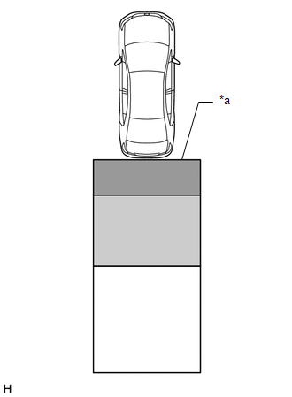
|
*a | Detection Area |
 |
Detection Area A |
 |
Detection Area B |
 |
Detection Area C |
|
Detection Area | Buzzer Operation |
Pedestrian Detection Icon |
|
A | Sounds repeatedly |
Blinks 3 times and then stays on |
|
B |
- When the vehicle is stationary: Sounds 3 times
- When the vehicle is backing up: Sounds repeatedly
| Blinks 3 times and then stays on |
|
C | When it is determined that a pedestrian will enter area A within a few seconds: Sounds repeatedly |
When it is determined that a pedestrian will enter area A within a few seconds: Blinks 3 times and then stays on |
HINT:
- Absolute Detection Area (3.0 m (9.8 ft.) from the edge of bumper, 3.0 m (9.8 ft.) wide
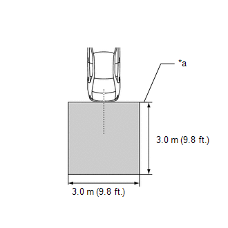
|
*a |
Edge of Bumper |
 |
Absolute Detection Area |
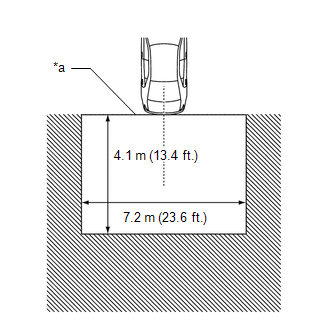
|
*a |
Edge of Bumper |
 |
Absolute No Detection Area |
Absolute No Detection Area (4.1 m (13.4 ft.) from the edge of the bumper, 7.2 m (23.6 ft.) wide)
COMMUNICATION SYSTEM OUTLINE
(a) CAN communication system
(1)
The panoramic view monitor system uses CAN communication for data
communications between the parking assist ECU and each ECU.
(2)
If a problem occurs in the CAN communication line, the parking assist
ECU outputs a CAN communication malfunction DTC. (To check, use the
Techstream.)
Click here 
(3)
If a problem occurs in the CAN communication line, the parking assist
ECU outputs a CAN communication malfunction DTC. (To check, use the
radio and display receiver assembly diagnosis screen.)
Click here

(4)
If a CAN communication line malfunction DTC is output, repair the
malfunction in the communication line and troubleshoot the panoramic
view monitor system when data communication is normal.
(5) Since the CAN communication line has its own length and route, it cannot be repaired temporarily with a bypass wire, etc.
VIDEO SIGNALS
(a) Video signal circuit
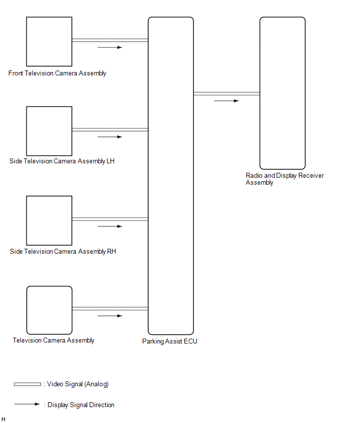
(1)
Video signals from the front television camera assembly are input into
the parking assist ECU via analog communication lines (vehicle wire
harness).
(2) Video signals from the side
television camera assembly LH are input into the parking assist ECU via
analog communication lines (vehicle wire harness).
(3)
Video signals from the side television camera assembly RH are input
into the parking assist ECU via analog communication lines (vehicle wire
harness).
(4) Video signals from the television
camera assembly are input into the parking assist ECU via analog
communication lines (vehicle wire harness).
(5)
Video signals from the parking assist ECU are input into the radio and
display receiver assembly via analog communication lines (vehicle wire
harness).
(b) Screen display
(1)
Video signals input from each camera are processed in the parking
assist ECU and displayed on the radio and display receiver assembly as
the panoramic view monitor system screen.
DIAGNOSTIC FUNCTION OUTLINE
(a)
This panoramic view monitor system has a diagnostic function displayed
in the radio and display receiver assembly. This function enables the
calibration (adjustment and verification) of the panoramic view monitor
system.
Click here 
(b) The panoramic view monitor system can check the following items by using the Techstream.
|
Item | Proceed to |
|
DTC |
 |
|
Data List / Active Test |
 |
CALIBRATION
(a) Use the panoramic view monitor system diagnosis screen for calibration and checking of the panoramic view monitor system.
Click here 
NOTICE:
Part
replacement and work performed during servicing may require calibration
of the panoramic view monitor system and other systems.
Click here

System Diagram
SYSTEM DIAGRAM
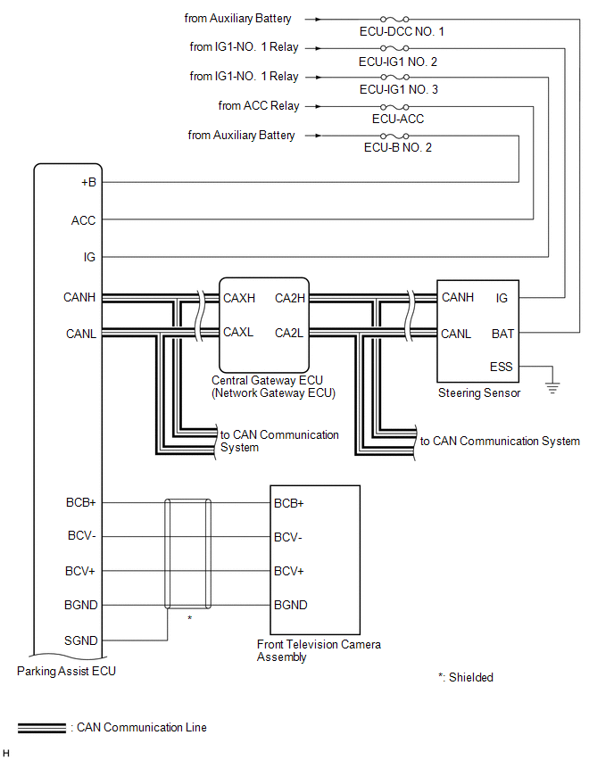
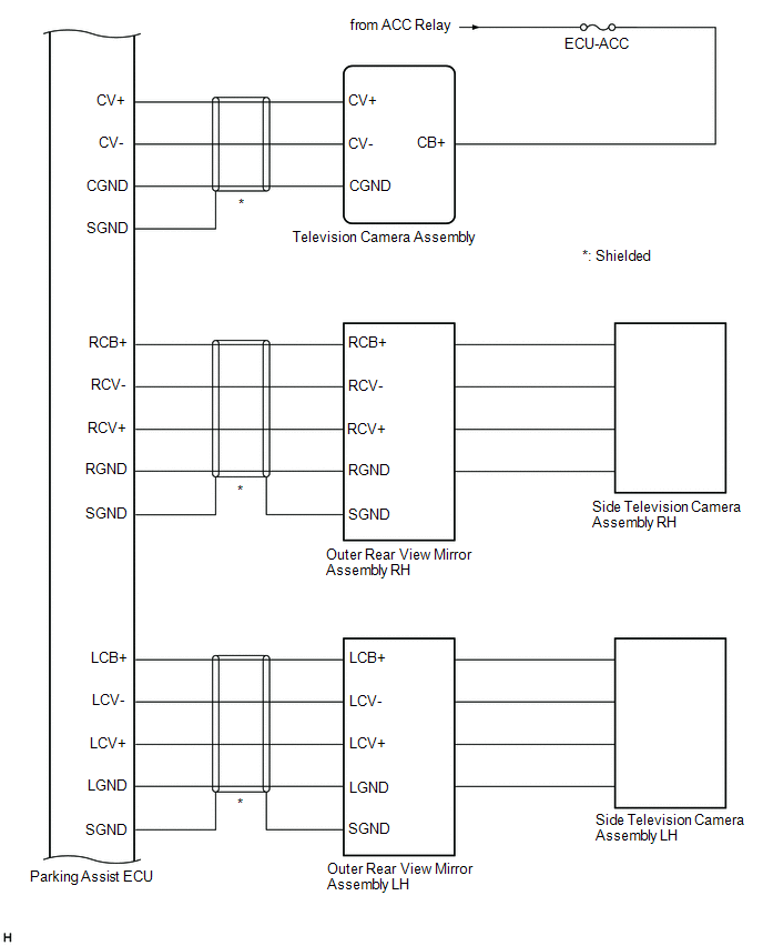
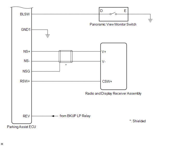
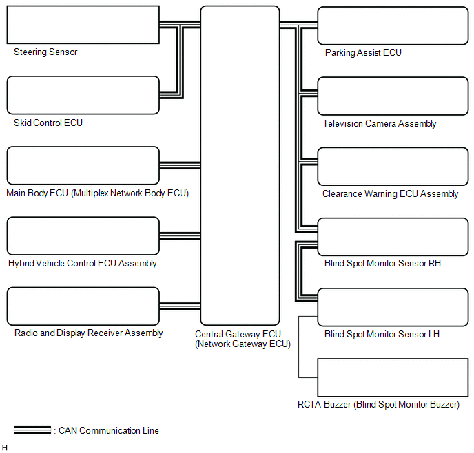
|
Sender | Receiver |
Signal | Line |
|
Steering Sensor | Parking Assist ECU |
- Data continuity flag
- Steering angle signal
| CAN |
|
Skid Control ECU | Parking Assist ECU |
- Wheel speed signal
- Vehicle speed signal
| CAN |
|
Main Body ECU (Multiplex Network Body ECU) |
Parking Assist ECU |
- Courtesy light switch signal
- Outer mirror retract information
- Destination signal
- Steering wheel signal
- Vehicle information
| CAN |
|
Hybrid Vehicle Control ECU Assembly |
Parking Assist ECU |
- Shift lever position signal
- Drivetrain information
- 2WD/AWD information
- HV flag
| CAN |
|
Clearance Warning ECU Assembly |
Parking Assist ECU | Sonar information signal |
CAN |
| Blind Spot Monitor Sensor RH |
- Parking Assist ECU
- Television Camera Assembly
| RCTA information signal |
CAN |
| Television Camera Assembly |
Blind Spot Monitor Sensor RH |
Camera detection buzzer request |
CAN |
Terminals Of Ecu
TERMINALS OF ECU
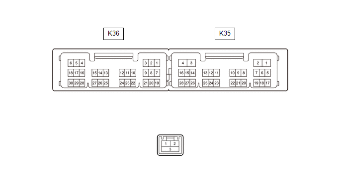
PARKING ASSIST ECU
(a) Disconnect the K35 parking assist ECU connector.
(b) Measure the voltage and resistance according to the value(s) in the table below.
|
Terminal No. (Symbol) | Wiring Color |
Terminal Description | Condition |
Specified Condition |
|
K35-2 (+B) - K35-3 (GND1) |
R - W-B | Power source signal |
Power switch off | 11 to 14 V |
|
K35-3 (GND1) - Body ground |
W-B - Body ground | Ground |
Always | Below 1 Ω |
|
K35-6 (IG) - K35-3 (GND1) |
BE - W-B |
IG power source signal |
Power switch on (IG) |
11 to 14 V |
|
Power switch off | Below 1 V |
|
K35-1 (ACC) - K35-3 (GND1) |
L - W-B | ACC power source signal |
Power switch on (ACC) |
11 to 14 V |
|
Power switch off | Below 1 V |
(c) Reconnect the K35 parking assist ECU connector.
(d) Measure the voltage, resistance and waveform according to the value(s) in the table below.
|
Terminal No. (Symbol) | Wiring Color |
Terminal Description | Condition |
Specified Condition |
|
K36-1 (CV+) - K36-9 (CGND) |
B - W | Television camera assembly display signal input |
Power switch on (IG) with the camera lens of the television camera assembly not covered, displaying the panoramic image |
Pulse generation (See waveform 1) |
|
Power switch on (IG) with the camera lens of the television camera assembly covered, blacking out the panoramic image |
Pulse generation (See waveform 2) |
|
K36-2 (CV-) - K35-3 (GND1) |
R - W-B | Television camera assembly ground |
Always | Below 1 Ω |
|
K36-4 (RCV+) - K36-18 (RGND) |
W - G | Side television camera assembly RH display signal input |
Power switch on (IG) with the camera lens of the side television camera assembly RH not covered, displaying the panoramic image |
Pulse generation (See waveform 1) |
|
Power switch on (IG) with the camera lens of the side television camera assembly RH covered, blacking out the panoramic image |
Pulse generation (See waveform 2) |
|
K36-5 (RCV-) - K35-3 (GND1) |
R - W-B | Side television camera assembly RH ground |
Always | Below 1 Ω |
|
K36-6 (RCB+) - K36-18 (RGND) |
B - G | Power source to side television camera assembly RH |
Power switch on (ACC) |
5.5 to 7.05 V |
|
K36-7 (RSW+) - K35-3 (GND1) |
BE - W-B | Terminal required by law |
Panoramic image being displayed |
0 to 2 V |
| Panoramic image not being displayed |
5.5 to 7.05 V |
|
K36-8 (SGND) - Body ground |
V - Body ground | Television camera assembly ground (shield) |
Always | Below 1 Ω |
|
K36-9 (CGND) - Body ground |
W - Body ground | Television camera assembly ground |
Always | Below 1 Ω |
|
K36-10 (LCV+) - K36-24 (LGND) |
W - G | Side television camera assembly LH display signal input |
Power switch on (IG) with the camera lens of the side television camera assembly LH not covered, displaying the panoramic image |
Pulse generation (See waveform 1) |
|
Power switch on (IG) with the camera lens of the side television camera assembly LH covered, blacking out the panoramic image |
Pulse generation (See waveform 2) |
|
K36-11 (LCV-) - K35-3 (GND1) |
R - W-B | Side television camera assembly LH ground |
Always | Below 1 Ω |
|
K36-12 (LCB+) - K36-24 (LGND) |
B - G | Power source to side television camera assembly LH |
Power switch on (ACC) |
5.5 to 7.05 V |
|
K36-13 (BCV+) - K36-27 (BGND) |
B - R | Front television camera assembly display signal input |
Power switch on (IG) with the camera lens of the front television camera assembly not covered, displaying the panoramic image |
Pulse generation (See waveform 1) |
|
Power switch on (IG) with the camera lens of the front television camera assembly covered, blacking out the panoramic image |
Pulse generation (See waveform 2) |
|
K36-14 (BCV-) - K35-3 (GND1) |
W - W-B | Front television camera assembly ground |
Always | Below 1 Ω |
|
K36-15 (BCB+) - K36-27 (BGND) |
G - R | Power source to front television camera assembly |
Power switch on (ACC) |
5.5 to 7.05 V |
|
K36-16 (SGND) - Body ground |
BR - Body ground | Side television camera assembly RH ground (shield) |
Always | Below 1 Ω |
|
K36-18 (RGND) - Body ground |
G - Body ground | Side television camera assembly RH ground |
Always | Below 1 Ω |
|
K36-23 (SGND) - Body ground |
BR - Body ground | Side television camera assembly LH ground (shield) |
Always | Below 1 Ω |
|
K36-24 (LGND) - Body ground |
G - Body ground | Side television camera assembly LH ground |
Always | Below 1 Ω |
|
K36-25 (SGND) - Body ground |
BR - Body ground | Front television camera assembly ground (shield) |
Always | Below 1 Ω |
|
K36-27 (BGND) - Body ground |
R - Body ground | Front television camera assembly ground |
Always | Below 1 Ω |
|
K35-15 (REV) - K35-3 (GND1) |
GR - W-B |
Reverse signal | Power switch on (IG), shift lever in P |
Below 1 V |
|
Power switch on (IG), shift lever in other than P |
11 to 14 V |
|
K35-20 (BLSW) - K35-3 (GND1) |
G - W-B | Panoramic view monitor switch switch signal |
Power switch on (IG), panoramic view monitor switch not pushed |
5.5 to 6.5 V |
|
Power switch on (IG), panoramic view monitor switch pushed |
Below 1 V |
|
K35-28 (NS+) - K35-27 (NSG) |
B - BR | Video signal |
Power switch on (IG) and panoramic image being displayed |
Pulse generation (See waveform 3) |
|
K35-26 (NS-) - K35-3 (GND1) |
W - W-B | Ground |
Always | Below 1 Ω |
|
K35-27 (NSG) - Body ground |
BR - Body ground | Shield ground |
Always | Below 1 Ω |
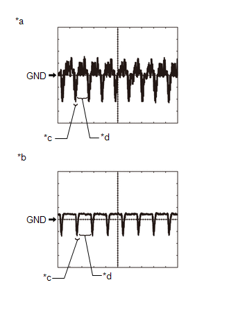
|
*a | Waveform 1 (camera lens is not covered, displaying an image) |
|
*b | Waveform 2 (camera lens is covered, blacking out the screen) |
|
*c | Synchronization Signal |
|
*d | Video Waveform |
(e) Reference (Oscilloscope waveform):
HINT:
A
waterproof connector is used for the television camera assembly, front
television camera assembly, side television camera assembly LH or side
television camera assembly RH. Therefore, inspect the waveform at the
radio and display receiver assembly with the connector connected.
(1) Waveform 1 (camera lens is not covered, displaying an image)
|
Item | Content |
|
Measurement terminal |
- K36-1 (CV+) - K36-9 (CGND)
- K36-10 (LCV+) - K36-24 (LGND)
- K36-13 (BCV+) - K36-27 (BGND)
- K36-4 (RCV+) - K36-18 (RGND)
|
| Measurement setting |
200 mV/DIV., 50 ÎĽs./DIV. |
|
Condition | Panoramic view monitor system operating |
HINT:
- The video waveform changes according to the image sent by the television
camera assembly, front television camera assembly, side television
camera assembly LH or side television camera assembly RH.
- The video waveform is constantly output when the power switch is on (ACC).
(2) Waveform 2 (camera lens is covered, blacking out the screen)
|
Item | Content |
|
Measurement terminal |
- K36-1 (CV+) - K36-9 (CGND)
- K36-10 (LCV+) - K36-24 (LGND)
- K36-13 (BCV+) - K36-27 (BGND)
- K36-4 (RCV+) - K36-18 (RGND)
|
| Measurement setting |
200 mV/DIV., 50 ÎĽs./DIV. |
|
Condition | Panoramic view monitor system operating |
HINT:
- The video waveform changes according to the image sent by the television
camera assembly, front television camera assembly, side television
camera assembly LH or side television camera assembly RH.
- The video waveform is constantly output when the power switch is on (ACC).
(3) Waveform 3
|
Item | Content |
|
Measurement terminal |
K35-28 (NS+) - K35-27 (NSG) |
|
Measurement setting | 200 mV/DIV., 50 ÎĽs./DIV. |
|
Condition | Panoramic image being displayed |
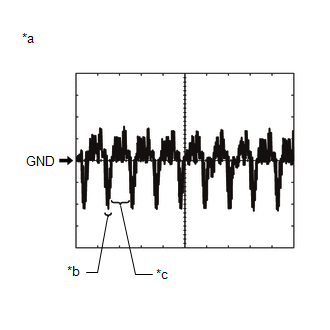
|
*a | Waveform 1 (camera lens is not covered, displaying an image) |
|
*b | Synchronization Signal |
|
*c | Video Waveform |
HINT:
The video waveform changes according to the image sent by the parking assist ECU.
TELEVISION CAMERA ASSEMBLY
(a) Disconnect the P7 television camera assembly connector.

(b) Measure the voltage on the wire harness side connector according to the value(s) in the table below.
|
Terminal No. (Symbol) | Wiring Color |
Terminal Description | Condition |
Specified Condition |
|
P7-6 (CB+) - Body ground |
L - Body ground | Power source |
Power switch on (ACC) |
11 to 14 V |
If the result is not as specified, there may be a malfunction on the wire harness side.
(c) Reconnect the P7 television camera assembly connector.
(d) Measure the voltage and waveform according to the value(s) in the table below.
|
Terminal No. (Symbol) | Wiring Color |
Terminal Description | Condition |
Specified Condition |
|
P7-3 (CV+) - P7-2 (CV-) |
B - R | Video signal |
Power switch on (IG) with the camera lens of the side television camera assembly RH not covered, displaying the panoramic image |
Pulse generation (Refer to waveform 1) |
|
Power switch on (IG) with the camera lens of the television camera assembly covered, blacking out the panoramic image |
Pulse generation (Refer to waveform 2) |
|
P7-5 (CGND) - Body ground |
W - Body ground | Shield ground |
Always | Below 1 V |
HINT:
A
waterproof connector is used for the television camera assembly.
Therefore, inspect the waveform at the radio and display receiver
assembly with the connector connected.
If the result is not as specified, the television camera assembly may be malfunctioning.
(e) Reference (Oscilloscope waveform):

|
*a | Waveform 1 (camera lens is not covered, displaying an image) |
|
*b | Waveform 2 (camera lens is covered, blacking out the screen) |
|
*c | Synchronization Signal |
|
*d | Video Waveform |
HINT:
A
waterproof connector is used for the television camera assembly.
Therefore, inspect the waveform at the radio and display receiver
assembly with the connector connected.
(1) Waveform 1 (camera lens is not covered, displaying an image)
|
Item | Content |
|
Measurement terminal |
P7-3 (CV+) - P7-2 (CV-) |
|
Measurement setting | 200 mV/DIV., 50 ÎĽs./DIV. |
|
Condition | Panoramic view monitor system operating |
HINT:
- The video waveform changes according to the image sent by the television camera assembly.
- The video waveform is constantly output when the power switch is on (ACC).
(2) Waveform 2 (camera lens is covered, blacking out the screen)
|
Item | Content |
|
Measurement terminal |
P7-3 (CV+) - P7-2 (CV-) |
|
Measurement setting | 200 mV/DIV., 50 ÎĽs./DIV. |
|
Condition | Panoramic view monitor system operating |
HINT:
- The video waveform changes according to the image sent by the television camera assembly.
- The video waveform is constantly output when the power switch is on (ACC).
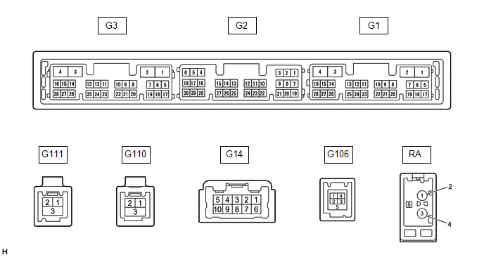
RADIO AND DISPLAY RECEIVER ASSEMBLY
(a) Measure the resistance and waveform according to the value(s) in the table below.
|
Terminal No. (Symbol) | Wiring Color |
Terminal Description | Condition |
Specified Condition |
|
G2-28 (V+) - G3-1 (GND1) |
V - BR | Video signal |
Panoramic image being displayed |
Pulse generation (Refer to waveform 1) |
|
G2-29 (V-) - G3-1 (GND1) |
SB - BR | Ground |
Always | Below 1 Ω |
(b) Reference (Oscilloscope waveform):
(1) Waveform 1
|
Item | Content |
|
Measurement terminal |
G2-28 (V+) - G3-1 (GND1) |
|
Measurement setting | 200 mV/DIV., 50 ÎĽs./DIV. |
|
Condition | Panoramic image being displayed |

|
*a | Waveform 1 (camera lens is not covered, displaying an image) |
|
*b | Synchronization Signal |
|
*c | Video Waveform |
HINT:
The video waveform changes according to the image sent by the parking assist ECU.
Lost Communication with Panoramic View Monitor Control Module (U023B)
DESCRIPTION
These DTCs are stored if there is a malfunction in the CAN communication system connected to the television camera assembly.
HINT:
If CAN communication system DTCs are stored, they may also be stored in other systems.
|
DTC No. | Detection Item |
DTC Detection Condition | Trouble Area |
DTC Output from |
|
U023B | Lost Communication with Panoramic View Monitor Control Module |
Lost Communication with parking assist ECU |
CAN communication system |
Television camera assembly |
PROCEDURE
(a) Clear the DTCs.
Chassis > Parking Assist Camera > Clear DTCs
(b) Recheck for DTCs and check that no DTCs are output.
Chassis > Parking Assist Camera > Trouble Codes
HINT:
- If CAN communication system DTCs are stored, they may also be stored in other systems.
- If the CAN communication system has been inspected and repaired in other
systems, the DTCs will not be output when rechecking for DTCs.
- If these DTCs are output frequently, duplicate the conditions that cause
the problem symptoms and perform troubleshooting again, even if the DTC
was not output when rechecking for DTCs.
Click here 
|
Result | Proceed to |
|
DTCs are output | A |
|
No DTCs are output | B |
| A |
 | GO TO CAN COMMUNICATION SYSTEM |
| B |
 | USE SIMULATION METHOD TO CHECK |
Control Module Communication Bus Off (U0073,U0265,U1110)
DESCRIPTION
These DTCs are stored if there is a malfunction in the CAN communication system connected to the parking assist ECU.
HINT:
If CAN communication system DTCs are stored, they may also be stored in other systems.
|
DTC No. | Detection Item |
DTC Detection Condition | Trouble Area |
DTC Output from |
|
U0073 | Control Module Communication Bus Off |
Control module communication bus off |
CAN communication system |
Parking assist ECU |
|
U0265 | Lost Communication with Image Processing Sensor A |
Lost Communication with television camera assembly |
CAN communication system |
Parking assist ECU |
|
U1110 | Lost Communication with Clearance Warning ECU |
Lost communication with clearance warning ECU assembly |
CAN communication system |
Parking assist ECU |
PROCEDURE
(a) Clear the DTCs.
Chassis > Panoramic View Monitor > Clear DTCs
(b) Check for DTCs.
Chassis > Panoramic View Monitor > Trouble Codes
| Result |
Proceed to |
| DTCs are output |
A |
| No DTCs are output |
B |
HINT:
- If CAN communication system DTCs are stored, they may also be stored in other systems.
- If the CAN communication system has been inspected and repaired in other
systems, the DTCs will not be output when rechecking for DTCs.
- If these DTCs are output frequently, duplicate the conditions that cause
the problem symptoms and perform troubleshooting again, even if the DTC
was not output when rechecking for DTCs.
Click here 
| A |
 | GO TO CAN COMMUNICATION SYSTEM |
| B |
 | USE SIMULATION METHOD TO CHECK |
Lost Communication with ECM / PCM "A" (U0100,U0126,U0129,U0140,U0163,U0233)
DESCRIPTION
- These DTCs are stored if there is a malfunction in the CAN communication system connected to the parking assist ECU.
- These DTCs are stored if there is a malfunction in the CAN communication system connected to the television camera assembly.
HINT:
If CAN communication system DTCs are stored, they may also be stored in other systems.
Parking Assist ECU |
DTC No. | Detection Item |
DTC Detection Condition | Trouble Area |
DTC Output from |
|
U0100 | Lost Communication with ECM / PCM "A" |
Lost Communication with hybrid vehicle control ECU assembly |
CAN communication system |
Parking assist ECU |
|
U0126 | Lost Communication with Steering Angle Sensor Module |
Lost communication with steering sensor |
CAN communication system |
Parking assist ECU |
|
U0129 | Lost Communication with Brake System Control Module |
Lost communication with skid control ECU |
CAN communication system |
Parking assist ECU |
|
U0140 | Lost Communication with Body Control Module |
Lost communication with main body ECU (multiplex network body ECU) |
CAN communication system |
Parking assist ECU |
|
U0163 | Lost Communication with Navigation Control Module |
Lost communication with radio and display receiver assembly |
CAN communication system |
Parking assist ECU |
|
U0233 | Lost Communication with Blind Spot Monitor Master Module |
Lost communication with blind spot monitor sensor RH |
CAN communication system |
Parking assist ECU |
Television Camera Assembly |
DTC No. | Detection Item |
DTC Detection Condition | Trouble Area |
DTC Output from |
|
U0100 | Lost Communication with ECM / PCM "A" |
Lost Communication with hybrid vehicle control ECU assembly |
CAN communication system |
Television camera assembly |
|
U0126 | Lost Communication with Steering Angle Sensor Module |
Lost communication with steering sensor |
CAN communication system |
Television camera assembly |
|
U0129 | Lost Communication with Brake System Control Module |
Lost communication with skid control ECU |
CAN communication system |
Television camera assembly |
|
U0140 | Lost Communication with Body Control Module |
Lost communication with main body ECU (multiplex network body ECU) |
CAN communication system |
Television camera assembly |
|
U0163 | Lost Communication with Navigation Control Module |
Lost communication with radio and display receiver assembly |
CAN communication system |
Television camera assembly |
|
U0233 | Lost Communication with Blind Spot Monitor Master Module |
Lost communication with blind spot monitor sensor RH |
CAN communication system |
Television camera assembly |
PROCEDURE
(a) Clear the DTCs.
Chassis > Panoramic View Monitor > Clear DTCs Chassis > Parking Assist Camera > Clear DTCs
(b) Recheck for DTCs and check that no DTCs are output.
Chassis > Panoramic View Monitor > Trouble Codes Chassis > Parking Assist Camera > Trouble Codes
HINT:
- If CAN communication system DTCs are stored, they may also be stored in other systems.
- If the CAN communication system has been inspected and repaired in other
systems, the DTCs will not be output when rechecking for DTCs.
- If these DTCs are output frequently, duplicate the conditions that cause
the problem symptoms and perform the troubleshooting again, even if the
DTC was not output when rechecking for DTCs.
Click here 
|
Result | Proceed to |
|
DTCs are output | A |
|
No DTCs are output | B |
| A |
 | GO TO CAN COMMUNICATION SYSTEM |
| B |
 | USE SIMULATION METHOD TO CHECK |
CAN Communication Failure (Message Registry) (U1000)
DESCRIPTION
If DTC U1000 is
stored frequently, duplicate the problem symptoms and perform
troubleshooting again even if the DTC is not output when rechecking for
DTCs.
Parking Assist ECU |
DTC No. | Detection Item |
DTC Detection Condition | Trouble Area |
DTC Output from |
|
U1000 | CAN Communication Failure (Message Registry) |
ECU malfunction | Parking assist ECU |
Parking assist ECU |
Television Camera Assembly |
DTC No. | Detection Item |
DTC Detection Condition | Trouble Area |
DTC Output from |
|
U1000 | CAN Communication Failure (Message Registry) |
ECU malfunction | Television camera assembly |
Television camera assembly |
PROCEDURE
(a) Clear the DTCs.
Chassis > Panoramic View Monitor > Clear DTCs Chassis > Parking Assist Camera > Clear DTCs
(b) Check for DTCs.
Chassis > Panoramic View Monitor > Trouble Codes Chassis > Parking Assist Camera > Trouble Codes
|
Result | Proceed to |
|
No DTCs are output | A |
|
DTC U1000 is output ("Panoramic View Monitor") |
B |
| DTC U1000 is output ("Parking Assist Camera") |
C |
HINT:
If
these DTCs are output frequently, duplicate the conditions that cause
the problem symptoms and perform troubleshooting again, even if the DTC
was not output when rechecking for DTCs.
Click here

| A |  |
USE SIMULATION METHOD TO CHECK |
| B |
 | REPLACE PARKING ASSIST ECU |
| C |
 | REPLACE TELEVISION CAMERA ASSEMBLY |


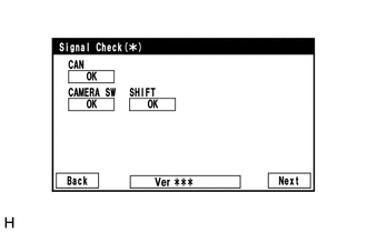


 Two-side View Screen Description


