Front Left Sensor Malfunction (C1AE1)
DESCRIPTION
The front
corner ultrasonic sensor LH is installed to the front bumper. The
clearance warning ECU assembly detects obstacles based on signals
received from the front corner ultrasonic sensor LH. If the front corner
ultrasonic sensor LH has an open circuit or other malfunction, it will
not function normally.
|
DTC No. | Detection Item |
DTC Detection Condition | Trouble Area |
|
C1AE1 | Front Left Sensor Malfunction |
A malfunction of the front corner ultrasonic sensor LH. |
- Front corner ultrasonic sensor LH
- Clearance warning ECU assembly
|
CAUTION / NOTICE / HINT
NOTICE:
If
DTCs are output after repairs, turn the engine switch on (IG) and the
intuitive parking assist system on. Then clear the DTCs.
Click here

PROCEDURE
(a) Check for DTCs.
Body Electrical > Advanced Parking Guidance/ICS/Intuitive P/A > Trouble Codes
|
Result | Proceed to |
|
Only DTC C1AE1 is output |
A |
| DTC C1AE1 and C1AEC are output |
B |
| No DTCs are output |
C |
| B |
 | GO TO DTC (C1AEC) |
| C |
| USE SIMULATION METHOD TO CHECK |
|
A |
 | |
| 2. |
REPLACE FRONT CORNER ULTRASONIC SENSOR LH |
(a) Replace the front corner ultrasonic sensor LH with a known good one.
Click here
HINT:
All
of the sensors are interchangeable. To confirm whether a sensor is
functioning normally, switch it with a known good sensor from the other
end of the vehicle.
|
NEXT | |
| |
(a) Clear the DTCs.
Body Electrical > Advanced Parking Guidance/ICS/Intuitive P/A > Clear DTCs
(b) Check for DTCs.
Body Electrical > Advanced Parking Guidance/ICS/Intuitive P/A > Trouble Codes
|
Result | Proceed to |
|
DTC C1AE1 is output | A |
|
No DTCs are output | B |
| A |
| REPLACE CLEARANCE WARNING ECU ASSEMBLY |
| B |
| END (FRONT LEFT SENSOR WAS DEFECTIVE) |
Front Left Center Sensor (C1AE2)
DESCRIPTION
The front
center ultrasonic sensor LH is installed to the front bumper. The
clearance warning ECU assembly detects obstacles based on signals
received from the front center ultrasonic sensor LH. If the front center
ultrasonic sensor LH has an open circuit or other malfunction, it will
not function normally.
|
DTC No. | Detection Item |
DTC Detection Condition | Trouble Area |
|
C1AE2 | Front Left Center Sensor |
A malfunction of the front center ultrasonic sensor LH. |
- Front center ultrasonic sensor LH
- Clearance warning ECU assembly
|
CAUTION / NOTICE / HINT
NOTICE:
If
DTCs are output after repairs, turn the engine switch on (IG) and the
intuitive parking assist system on. Then clear the DTCs.
Click here

PROCEDURE
(a) Check for DTCs.
Body Electrical > Advanced Parking Guidance/ICS/Intuitive P/A > Trouble Codes
|
Result | Proceed to |
|
Only DTC C1AE2 is output |
A |
| DTC C1AE2 and C1AEC are output |
B |
| No DTCs are output |
C |
| B |
 | GO TO DTC (C1AEC) |
| C |
| USE SIMULATION METHOD TO CHECK |
|
A |
 | |
| 2. |
REPLACE FRONT CENTER ULTRASONIC SENSOR LH |
(a) Replace the front center ultrasonic sensor LH with a known good one.
Click here
HINT:
All
of the sensors are interchangeable. To confirm whether a sensor is
functioning normally, switch it with a known good sensor from the other
end of the vehicle.
|
NEXT | |
| |
(a) Clear the DTCs.
Body Electrical > Advanced Parking Guidance/ICS/Intuitive P/A > Clear DTCs
(b) Check for DTCs.
Body Electrical > Advanced Parking Guidance/ICS/Intuitive P/A > Trouble Codes
|
Result | Proceed to |
|
DTC C1AE2 is output | A |
|
No DTCs are output | B |
| A |
| REPLACE CLEARANCE WARNING ECU ASSEMBLY |
| B |
| END (FRONT LEFT CENTER SENSOR WAS DEFECTIVE) |
Front Right Center Sensor (C1AE3)
DESCRIPTION
The front
center ultrasonic sensor RH is installed to the front bumper. The
clearance warning ECU assembly detects obstacles based on signals
received from the front center ultrasonic sensor RH. If the front center
ultrasonic sensor RH has an open circuit or other malfunction, it will
not function normally.
|
DTC No. | Detection Item |
DTC Detection Condition | Trouble Area |
|
C1AE3 | Front Right Center Sensor |
A malfunction of the front center ultrasonic sensor RH. |
- Front center ultrasonic sensor RH
- Clearance warning ECU assembly
|
CAUTION / NOTICE / HINT
NOTICE:
If
DTCs are output after repairs, turn the engine switch on (IG) and the
intuitive parking assist system on. Then clear the DTCs.
Click here

PROCEDURE
(a) Check for DTCs.
Body Electrical > Advanced Parking Guidance/ICS/Intuitive P/A > Trouble Codes
|
Result | Proceed to |
|
Only DTC C1AE3 is output |
A |
| DTC C1AE3 and C1AEC are output |
B |
| No DTCs are output |
C |
| B |
 | GO TO DTC (C1AEC) |
| C |
| USE SIMULATION METHOD TO CHECK |
|
A |
 | |
| 2. |
REPLACE FRONT CENTER ULTRASONIC SENSOR RH |
(a) Replace the front center ultrasonic sensor RH with a known good one.
Click here
HINT:
All
of the sensors are interchangeable. To confirm whether a sensor is
functioning normally, switch it with a known good sensor from the other
end of the vehicle.
|
NEXT | |
| |
(a) Clear the DTCs.
Body Electrical > Advanced Parking Guidance/ICS/Intuitive P/A > Clear DTCs
(b) Check for DTCs.
Body Electrical > Advanced Parking Guidance/ICS/Intuitive P/A > Trouble Codes
|
Result | Proceed to |
|
DTC C1AE3 is output | A |
|
No DTCs are output | B |
| A |
| REPLACE CLEARANCE WARNING ECU ASSEMBLY |
| B |
| END (FRONT RIGHT CENTER SENSOR WAS DEFECTIVE) |
Front Right Sensor Malfunction (C1AE4)
DESCRIPTION
The front
corner ultrasonic sensor RH is installed to the front bumper. The
clearance warning ECU assembly detects obstacles based on signals
received from the front corner ultrasonic sensor RH. If the front corner
ultrasonic sensor RH has an open circuit or other malfunction, it will
not function normally.
|
DTC No. | Detection Item |
DTC Detection Condition | Trouble Area |
|
C1AE4 | Front Right Sensor Malfunction |
A malfunction of the front corner ultrasonic sensor RH. |
- Front corner ultrasonic sensor RH
- Clearance warning ECU assembly
|
CAUTION / NOTICE / HINT
NOTICE:
If
DTCs are output after repairs, turn the engine switch on (IG) and the
intuitive parking assist system on. Then clear the DTCs.
Click here

PROCEDURE
(a) Check for DTCs.
Body Electrical > Advanced Parking Guidance/ICS/Intuitive P/A > Trouble Codes
|
Result | Proceed to |
|
Only DTC C1AE4 is output |
A |
| DTC C1AE4 and C1AEC are output |
B |
| No DTCs are output |
C |
| B |
 | GO TO DTC (C1AEC) |
| C |
| USE SIMULATION METHOD TO CHECK |
|
A |
 | |
| 2. |
REPLACE FRONT CORNER ULTRASONIC SENSOR RH |
(a) Replace the front corner ultrasonic sensor RH with a known good one.
Click here
HINT:
All
of the sensors are interchangeable. To confirm whether a sensor is
functioning normally, switch it with a known good sensor from the other
end of the vehicle.
|
NEXT | |
| |
(a) Clear the DTCs.
Body Electrical > Advanced Parking Guidance/ICS/Intuitive P/A > Clear DTCs
(b) Check for DTCs.
Body Electrical > Advanced Parking Guidance/ICS/Intuitive P/A > Trouble Codes
|
Result | Proceed to |
|
DTC C1AE4 is output | A |
|
No DTCs are output | B |
| A |
| REPLACE CLEARANCE WARNING ECU ASSEMBLY |
| B |
| END (FRONT RIGHT SENSOR WAS DEFECTIVE) |
Rear Left Sensor Malfunction (C1AE6)
DESCRIPTION
The rear corner
ultrasonic sensor LH is installed to the rear bumper. The clearance
warning ECU assembly detects obstacles based on signals received from
the rear corner ultrasonic sensor LH. If the rear corner ultrasonic
sensor LH has an open circuit or other malfunction, it will not function
normally.
|
DTC No. | Detection Item |
DTC Detection Condition | Trouble Area |
|
C1AE6 | Rear Left Sensor Malfunction |
A malfunction of the rear corner ultrasonic sensor LH. |
- Rear corner ultrasonic sensor LH
- Clearance warning ECU assembly
|
CAUTION / NOTICE / HINT
NOTICE:
If
DTCs are output after repairs, turn the engine switch on (IG) and the
intuitive parking assist system on. Then clear the DTCs.
Click here

PROCEDURE
(a) Check for DTCs.
Body Electrical > Advanced Parking Guidance/ICS/Intuitive P/A > Trouble Codes
|
Result | Proceed to |
|
Only DTC C1AE6 is output |
A |
| DTC C1AE6 and C1AED are output |
B |
| No DTCs are output |
C |
| B |
 | GO TO DTC (C1AED) |
| C |
| USE SIMULATION METHOD TO CHECK |
|
A |
 | |
| 2. |
REPLACE REAR CORNER ULTRASONIC SENSOR LH |
(a) Replace the rear corner ultrasonic sensor LH with a known good one.
Click here
HINT:
All
of the sensors are interchangeable. To confirm whether a sensor is
functioning normally, switch it with a known good sensor from the other
end of the vehicle.
|
NEXT | |
| |
(a) Clear the DTCs.
Body Electrical > Advanced Parking Guidance/ICS/Intuitive P/A > Clear DTCs
(b) Check for DTCs.
Body Electrical > Advanced Parking Guidance/ICS/Intuitive P/A > Trouble Codes
|
Result | Proceed to |
|
DTC C1AE6 is output | A |
|
No DTCs are output | B |
| A |
| REPLACE CLEARANCE WARNING ECU ASSEMBLY |
| B |
| END (REAR LEFT SENSOR WAS DEFECTIVE) |
Rear Left Center Sensor Malfunction (C1AE7)
DESCRIPTION
The rear center
ultrasonic sensor LH is installed to the rear bumper. The clearance
warning ECU assembly detects obstacles based on signals received from
the rear center ultrasonic sensor LH. If the rear center ultrasonic
sensor LH has an open circuit or other malfunction, it will not function
normally.
|
DTC No. | Detection Item |
DTC Detection Condition | Trouble Area |
|
C1AE7 | Rear Left Center Sensor Malfunction |
A malfunction of the rear center ultrasonic sensor LH. |
- Rear center ultrasonic sensor LH
- Clearance warning ECU assembly
|
CAUTION / NOTICE / HINT
NOTICE:
If
DTCs are output after repairs, turn the engine switch on (IG) and the
intuitive parking assist system on. Then clear the DTCs.
Click here

PROCEDURE
(a) Check for DTCs.
Body Electrical > Advanced Parking Guidance/ICS/Intuitive P/A > Trouble Codes
|
Result | Proceed to |
|
Only DTC C1AE7 is output |
A |
| DTC C1AE7 and C1AED are output |
B |
| No DTCs are output |
C |
| B |
 | GO TO DTC (C1AED) |
| C |
| USE SIMULATION METHOD TO CHECK |
|
A |
 | |
| 2. |
REPLACE REAR CENTER ULTRASONIC SENSOR LH |
(a) Replace the rear center ultrasonic sensor LH with a known good one.
Click here
HINT:
All
of the sensors are interchangeable. To confirm whether a sensor is
functioning normally, switch it with a known good sensor from the other
end of the vehicle.
|
NEXT | |
| |
(a) Clear the DTCs.
Body Electrical > Advanced Parking Guidance/ICS/Intuitive P/A > Clear DTCs
(b) Check for DTCs.
Body Electrical > Advanced Parking Guidance/ICS/Intuitive P/A > Trouble Codes
|
Result | Proceed to |
|
DTC C1AE7 is output | A |
|
No DTCs are output | B |
| A |
| REPLACE CLEARANCE WARNING ECU ASSEMBLY |
| B |
| END (REAR LEFT CENTER SENSOR WAS DEFECTIVE) |
Rear Right Center Sensor Malfunction (C1AE8)
DESCRIPTION
The rear center
ultrasonic sensor RH is installed to the rear bumper. The clearance
warning ECU assembly detects obstacles based on signals received from
the rear center ultrasonic sensor RH. If the rear center ultrasonic
sensor RH has an open circuit or other malfunction, it will not function
normally.
|
DTC No. | Detection Item |
DTC Detection Condition | Trouble Area |
|
C1AE8 | Rear Right Center Sensor Malfunction |
A malfunction of the rear center ultrasonic sensor RH. |
- Rear center ultrasonic sensor RH
- Clearance warning ECU assembly
|
CAUTION / NOTICE / HINT
NOTICE:
If
DTCs are output after repairs, turn the engine switch on (IG) and the
intuitive parking assist system on. Then clear the DTCs.
Click here

PROCEDURE
(a) Check for DTCs.
Body Electrical > Advanced Parking Guidance/ICS/Intuitive P/A > Trouble Codes
|
Result | Proceed to |
|
Only DTC C1AE8 is output |
A |
| DTC C1AE8 and C1AED are output |
B |
| No DTCs are output |
C |
| B |
 | GO TO DTC (C1AED) |
| C |
| USE SIMULATION METHOD TO CHECK |
|
A |
 | |
| 2. |
REPLACE REAR CENTER ULTRASONIC SENSOR RH |
(a) Replace the rear center ultrasonic sensor RH with a known good one.
Click here
HINT:
All
of the sensors are interchangeable. To confirm whether a sensor is
functioning normally, switch it with a known good sensor from the other
end of the vehicle.
|
NEXT | |
| |
(a) Clear the DTCs.
Body Electrical > Advanced Parking Guidance/ICS/Intuitive P/A > Clear DTCs
(b) Check for DTCs.
Body Electrical > Advanced Parking Guidance/ICS/Intuitive P/A > Trouble Codes
|
Result | Proceed to |
|
DTC C1AE8 is output | A |
|
No DTCs are output | B |
| A |
| REPLACE CLEARANCE WARNING ECU ASSEMBLY |
| B |
| END (REAR RIGHT CENTER SENSOR WAS DEFECTIVE) |
Rear Right Sensor Malfunction (C1AE9)
DESCRIPTION
The rear corner
ultrasonic sensor RH is installed to the rear bumper. The clearance
warning ECU assembly detects obstacles based on signals received from
the rear corner ultrasonic sensor RH. If the rear corner ultrasonic
sensor RH has an open circuit or other malfunction, it will not function
normally.
|
DTC No. | Detection Item |
DTC Detection Condition | Trouble Area |
|
C1AE9 | Rear Right Sensor Malfunction |
A malfunction of the rear corner ultrasonic sensor RH. |
- Rear corner ultrasonic sensor RH
- Clearance warning ECU assembly
|
CAUTION / NOTICE / HINT
NOTICE:
If
DTCs are output after repairs, turn the engine switch on (IG) and the
intuitive parking assist system on. Then clear the DTCs.
Click here

PROCEDURE
(a) Check for DTCs.
Body Electrical > Advanced Parking Guidance/ICS/Intuitive P/A > Trouble Codes
|
Result | Proceed to |
|
Only DTC C1AE9 is output |
A |
| DTC C1AE9 and C1AED are output |
B |
| No DTCs are output |
C |
| B |
 | GO TO DTC (C1AED) |
| C |
| USE SIMULATION METHOD TO CHECK |
|
A |
 | |
| 2. |
REPLACE REAR CORNER ULTRASONIC SENSOR RH |
(a) Replace the rear corner ultrasonic sensor RH with a known good one.
Click here
HINT:
All
of the sensors are interchangeable. To confirm whether a sensor is
functioning normally, switch it with a known good sensor from the other
end of the vehicle.
|
NEXT | |
| |
(a) Clear the DTCs.
Body Electrical > Advanced Parking Guidance/ICS/Intuitive P/A > Clear DTCs
(b) Check for DTCs.
Body Electrical > Advanced Parking Guidance/ICS/Intuitive P/A > Trouble Codes
|
Result | Proceed to |
|
DTC C1AE9 is output | A |
|
No DTCs are output | B |
| A |
| REPLACE CLEARANCE WARNING ECU ASSEMBLY |
| B |
| END (REAR RIGHT SENSOR WAS DEFECTIVE) |
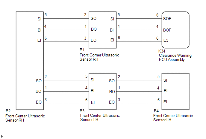
Front Sensor Communication Malfunction (C1AEC)
DESCRIPTION
This DTC is
stored when there is an open or short circuit in the communication line
between the front sensors and the ECU, or when there is a malfunction in
a front sensor.
|
DTC No. | Detection Item |
DTC Detection Condition | Trouble Area |
|
C1AEC | Front Sensor Communication Malfunction |
An
open or short circuit in the communication line between the front
sensors and ECU or a malfunction in a front sensor during initialization
mode after the engine switch is turned on (IG). |
- Front ultrasonic sensor circuit
- Harness or connector
- Clearance warning ECU assembly
|
WIRING DIAGRAM
PROCEDURE
| 1. |
INITIALIZE FRONT CENTER ULTRASONIC SENSOR AND FRONT CORNER ULTRASONIC SENSOR |
(a) Initialize the front center ultrasonic sensor and front corner ultrasonic sensor.
Click here 
|
NEXT |
 | |
| 2. |
CHECK DTC OUTPUT (C1AEC) |
(a) Check for DTCs.
Body Electrical > Advanced Parking Guidance/ICS/Intuitive P/A > Trouble Codes
(b) Clear the DTCs.
Body Electrical > Advanced Parking Guidance/ICS/Intuitive P/A > Clear DTCs
(c) Recheck for DTCs.
Body Electrical > Advanced Parking Guidance/ICS/Intuitive P/A > Trouble Codes
|
Result | Proceed to |
|
DTC C1AEC is output | A |
|
No DTCs are output | B |
| B |
 | USE SIMULATION METHOD TO CHECK |
|
A | |
| |
| 3. |
CHECK HARNESS AND CONNECTOR (CLEARANCE WARNING ECU ASSEMBLY - FRONT CORNER ULTRASONIC SENSOR RH) |
(a) Disconnect the K34 clearance warning ECU assembly connector.
(b) Disconnect the B1 front corner ultrasonic sensor RH.
(c) Measure the resistance according to the value(s) in the table below.
Standard Resistance:
|
Tester Connection | Condition |
Specified Condition |
|
K34-4 (BOF) - B1-4 (BI) |
Always | Below 1 Ω |
|
K34-8 (SOF) - B1-5 (SI) |
Always | Below 1 Ω |
|
K34-6 (E5) - B1-6 (EI) |
Always | Below 1 Ω |
|
K34-4 (BOF) or B1-4 (BI) - Body ground |
Always | 10 kΩ or higher |
|
K34-8 (SOF) or B1-5 (SI) - Body ground |
Always | 10 kΩ or higher |
|
K34-6 (E5) or B1-6 (EI) - Body ground |
Always | 10 kΩ or higher |
| NG |
| REPAIR OR REPLACE HARNESS OR CONNECTOR |
|
OK | |
| |
| 4. |
CHECK HARNESS AND CONNECTOR (FRONT CORNER ULTRASONIC SENSOR RH - FRONT CENTER ULTRASONIC SENSOR RH) |
(a) Disconnect the B2 front center ultrasonic sensor RH.
(b) Measure the resistance according to the value(s) in the table below.
Standard Resistance:
|
Tester Connection | Condition |
Specified Condition |
|
B1-1 (BO) - B2-4 (BI) |
Always | Below 1 Ω |
|
B1-2 (SO) - B2-5 (SI) |
Always | Below 1 Ω |
|
B1-3 (EO) - B2-6 (EI) |
Always | Below 1 Ω |
|
B1-1 (BO) or B2-4 (BI) - Body ground |
Always | 10 kΩ or higher |
|
B1-2 (SO) or B2-5 (SI) - Body ground |
Always | 10 kΩ or higher |
|
B1-3 (EO) or B2-6 (EI) - Body ground |
Always | 10 kΩ or higher |
| NG |
| REPAIR OR REPLACE HARNESS OR CONNECTOR |
|
OK | |
| |
| 5. |
CHECK HARNESS AND CONNECTOR (FRONT CENTER ULTRASONIC SENSOR RH - FRONT CENTER ULTRASONIC SENSOR LH) |
(a) Disconnect the B3 front center ultrasonic sensor LH.
(b) Measure the resistance according to the value(s) in the table below.
Standard Resistance:
|
Tester Connection | Condition |
Specified Condition |
|
B2-1 (BO) - B3-4 (BI) |
Always | Below 1 Ω |
|
B2-2 (SO) - B3-5 (SI) |
Always | Below 1 Ω |
|
B2-3 (EO) - B3-6 (EI) |
Always | Below 1 Ω |
|
B2-1 (BO) or B3-4 (BI) - Body ground |
Always | 10 kΩ or higher |
|
B2-2 (SO) or B3-5 (SI) - Body ground |
Always | 10 kΩ or higher |
|
B2-3 (EO) or B3-6 (EI) - Body ground |
Always | 10 kΩ or higher |
| NG |
| REPAIR OR REPLACE HARNESS OR CONNECTOR |
|
OK | |
| |
| 6. |
CHECK HARNESS AND CONNECTOR (FRONT CENTER ULTRASONIC SENSOR LH - FRONT CORNER ULTRASONIC SENSOR LH) |
(a) Disconnect the B4 front corner ultrasonic sensor LH.
(b) Measure the resistance according to the value(s) in the table below.
Standard Resistance:
|
Tester Connection | Condition |
Specified Condition |
|
B3-1 (BO) - B4-4 (BI) |
Always | Below 1 Ω |
|
B3-2 (SO) - B4-5 (SI) |
Always | Below 1 Ω |
|
B3-3 (EO) - B4-6 (EI) |
Always | Below 1 Ω |
|
B3-1 (BO) or B4-4 (BI) - Body ground |
Always | 10 kΩ or higher |
|
B3-2 (SO) or B4-5 (SI) - Body ground |
Always | 10 kΩ or higher |
|
B3-3 (EO) or B4-6 (EI) - Body ground |
Always | 10 kΩ or higher |
| NG |
| REPAIR OR REPLACE HARNESS OR CONNECTOR |
|
OK | |
| |
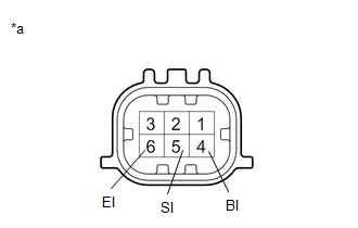
| 7. |
INSPECT FRONT CORNER ULTRASONIC SENSOR RH |
| (a) Measure the resistance according to the value(s) in the table below.
Standard Resistance: |
Tester Connection | Condition |
Specified Condition | |
4 (BI) - 6 (EI) | Always |
10 kΩ or higher | |
4 (BI) - 1 (BO) | Always |
Below 1 Ω | |
5 (SI) - 2 (SO) | Always |
Below 30 Ω | |
6 (EI) - 3 (EO) | Always |
Below 1 Ω | |
 |
|
*a | Component without harness connected
(Front Corner Ultrasonic Sensor RH) | | |
| NG |
| REPLACE FRONT CORNER ULTRASONIC SENSOR RH |
|
OK | |
| |
| 8. |
INSPECT FRONT CENTER ULTRASONIC SENSOR RH |
| (a) Measure the resistance according to the value(s) in the table below.
Standard Resistance: |
Tester Connection | Condition |
Specified Condition | |
4 (BI) - 6 (EI) | Always |
10 kΩ or higher | |
4 (BI) - 1 (BO) | Always |
Below 1 Ω | |
5 (SI) - 2 (SO) | Always |
Below 30 Ω | |
6 (EI) - 3 (EO) | Always |
Below 1 Ω | | |
|
|
*a | Component without harness connected
(Front Center Ultrasonic Sensor RH) | | |
| NG |
| REPLACE FRONT CENTER ULTRASONIC SENSOR RH |
|
OK | |
| |
| 9. |
INSPECT FRONT CENTER ULTRASONIC SENSOR LH |
| (a) Measure the resistance according to the value(s) in the table below.
Standard Resistance: |
Tester Connection | Condition |
Specified Condition | |
4 (BI) - 6 (EI) | Always |
10 kΩ or higher | |
4 (BI) - 1 (BO) | Always |
Below 1 Ω | |
5 (SI) - 2 (SO) | Always |
Below 30 Ω | |
6 (EI) - 3 (EO) | Always |
Below 1 Ω | | |
|
|
*a | Component without harness connected
(Front Center Ultrasonic Sensor LH) | | |
| NG |
| REPLACE FRONT CENTER ULTRASONIC SENSOR LH |
|
OK | |
| |
| 10. |
INSPECT FRONT CORNER ULTRASONIC SENSOR LH |
| (a) Measure the resistance according to the value(s) in the table below.
Standard Resistance: |
Tester Connection | Condition |
Specified Condition | |
4 (BI) - 6 (EI) | Always |
10 kΩ or higher | |
4 (BI) - 1 | Always |
Below 1 Ω | |
5 (SI) - 2 | Always |
Below 30 Ω | |
6 (EI) - 3 | Always |
Below 1 Ω | |
 |
|
*a | Component without harness connected
(Front Corner Ultrasonic Sensor LH) | | |
| NG |
| REPLACE FRONT CORNER ULTRASONIC SENSOR LH |
|
OK | |
| |
| 11. |
REPLACE FRONT CORNER ULTRASONIC SENSOR RH |
Click here
|
NEXT | |
| |
| 12. |
CHECK DTC OUTPUT (C1AEC) |
(a) Clear the DTCs.
Body Electrical > Advanced Parking Guidance/ICS/Intuitive P/A > Clear DTCs
(b) Check for DTCs.
Body Electrical > Advanced Parking Guidance/ICS/Intuitive P/A > Trouble Codes
|
Result | Proceed to |
|
DTC C1AEC is output | A |
|
No DTCs are output | B |
| B |
| END (FRONT CORNER ULTRASONIC SENSOR RH WAS DEFECTIVE) |
|
A | |
| |
| 13. |
REPLACE FRONT CENTER ULTRASONIC SENSOR RH |
Click here
|
NEXT | |
| |
| 14. |
CHECK DTC OUTPUT (C1AEC) |
(a) Clear the DTCs.
Body Electrical > Advanced Parking Guidance/ICS/Intuitive P/A > Clear DTCs
(b) Check for DTCs.
Body Electrical > Advanced Parking Guidance/ICS/Intuitive P/A > Trouble Codes
|
Result | Proceed to |
|
DTC C1AEC is output | A |
|
No DTCs are output | B |
| B |
| END (FRONT CENTER ULTRASONIC SENSOR RH WAS DEFECTIVE) |
|
A | |
| |
| 15. |
REPLACE FRONT CENTER ULTRASONIC SENSOR LH |
Click here
|
NEXT | |
| |
| 16. |
CHECK DTC OUTPUT (C1AEC) |
(a) Clear the DTCs.
Body Electrical > Advanced Parking Guidance/ICS/Intuitive P/A > Clear DTCs
(b) Check for DTCs.
Body Electrical > Advanced Parking Guidance/ICS/Intuitive P/A > Trouble Codes
|
Result | Proceed to |
|
DTC C1AEC is output | A |
|
No DTCs are output | B |
| B |
| END (FRONT CENTER ULTRASONIC SENSOR LH WAS DEFECTIVE) |
|
A | |
| |
| 17. |
REPLACE FRONT CORNER ULTRASONIC SENSOR LH |
Click here
|
NEXT | |
| |
| 18. |
CHECK DTC OUTPUT (C1AEC) |
(a) Clear the DTCs.
Body Electrical > Advanced Parking Guidance/ICS/Intuitive P/A > Clear DTCs
(b) Check for DTCs.
Body Electrical > Advanced Parking Guidance/ICS/Intuitive P/A > Trouble Codes
|
Result | Proceed to |
|
DTC C1AEC is output | A |
|
No DTCs are output | B |
| A |
| REPLACE CLEARANCE WARNING ECU ASSEMBLY |
| B |
| END (FRONT CORNER ULTRASONIC SENSOR LH WAS DEFECTIVE) |
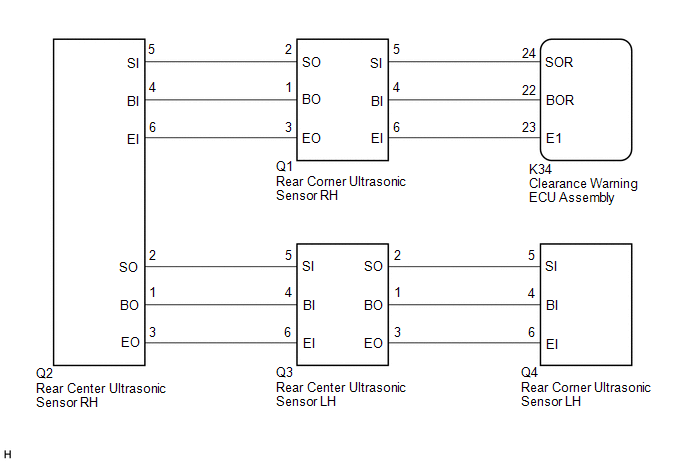
Rear Sensor Communication Malfunction (C1AED)
DESCRIPTION
This DTC is
stored when there is an open or short circuit in the communication line
between the rear sensors and the ECU, or when there is a malfunction in a
rear sensor.
|
DTC No. | Detection Item |
DTC Detection Condition | Trouble Area |
|
C1AED | Rear Sensor Communication Malfunction |
An
open or short circuit in the communication line between the rear
sensors and ECU or a malfunction in a rear sensor during initialization
mode after the engine switch is turned on (IG). |
- Rear ultrasonic sensor circuit
- Harness or connector
- Clearance warning ECU assembly
|
WIRING DIAGRAM
PROCEDURE
| 1. |
INITIALIZE REAR CENTER ULTRASONIC SENSOR AND REAR CORNER ULTRASONIC SENSOR |
(a) Initialize the rear center ultrasonic sensor and rear corner ultrasonic sensor.
Click here 
|
NEXT |
 | |
| 2. |
CHECK DTC OUTPUT (C1AED) |
(a) Check for DTCs.
Body Electrical > Advanced Parking Guidance/ICS/Intuitive P/A > Trouble Codes
(b) Clear the DTCs.
Body Electrical > Advanced Parking Guidance/ICS/Intuitive P/A > Clear DTCs
(c) Recheck for DTCs.
Body Electrical > Advanced Parking Guidance/ICS/Intuitive P/A > Trouble Codes
|
Result | Proceed to |
|
DTC C1AED is output | A |
|
No DTCs are output | B |
| B |
 | USE SIMULATION METHOD TO CHECK |
|
A | |
| |
| 3. |
CHECK HARNESS AND CONNECTOR (CLEARANCE WARNING ECU ASSEMBLY - REAR CORNER ULTRASONIC SENSOR RH) |
(a) Disconnect the K34 clearance warning ECU assembly connector.
(b) Disconnect the Q1 rear corner ultrasonic sensor RH.
(c) Measure the resistance according to the value(s) in the table below.
Standard Resistance:
|
Tester Connection | Condition |
Specified Condition |
|
K34-22 (BOR) - Q1-4 (BI) |
Always | Below 1 Ω |
|
K34-24 (SOR) - Q1-5 (SI) |
Always | Below 1 Ω |
|
K34-23 (E1) - Q1-6 (EI) |
Always | Below 1 Ω |
|
K34-22 (BOR) or Q1-4 (BI) - Body ground |
Always | 10 kΩ or higher |
|
K34-24 (SOR) or Q1-5 (SI) - Body ground |
Always | 10 kΩ or higher |
|
K34-23 (E1) or Q1-6 (EI) - Body ground |
Always | 10 kΩ or higher |
| NG |
| REPAIR OR REPLACE HARNESS OR CONNECTOR |
|
OK | |
| |
| 4. |
CHECK HARNESS AND CONNECTOR (REAR CORNER ULTRASONIC SENSOR RH - REAR CENTER ULTRASONIC SENSOR RH) |
(a) Disconnect the Q2 rear center ultrasonic sensor RH.
(b) Measure the resistance according to the value(s) in the table below.
Standard Resistance:
|
Tester Connection | Condition |
Specified Condition |
|
Q1-1 (BO) - Q2-4 (BI) |
Always | Below 1 Ω |
|
Q1-2 (SO) - Q2-5 (SI) |
Always | Below 1 Ω |
|
Q1-3 (EO) - Q2-6 (EI) |
Always | Below 1 Ω |
|
Q1-1 (BO) or Q2-4 (BI) - Body ground |
Always | 10 kΩ or higher |
|
Q1-2 (SO) or Q2-5 (SI) - Body ground |
Always | 10 kΩ or higher |
|
Q1-3 (EO) or Q2-6 (EI) - Body ground |
Always | 10 kΩ or higher |
| NG |
| REPAIR OR REPLACE HARNESS OR CONNECTOR |
|
OK | |
| |
| 5. |
CHECK HARNESS AND CONNECTOR (REAR CENTER ULTRASONIC SENSOR RH - REAR CENTER ULTRASONIC SENSOR LH) |
(a) Disconnect the Q3 rear center ultrasonic sensor LH.
(b) Measure the resistance according to the value(s) in the table below.
Standard Resistance:
|
Tester Connection | Condition |
Specified Condition |
|
Q2-1 (BO) - Q3-4 (BI) |
Always | Below 1 Ω |
|
Q2-2 (SO) - Q3-5 (SI) |
Always | Below 1 Ω |
|
Q2-3 (EO) - Q3-6 (EI) |
Always | Below 1 Ω |
|
Q2-1 (BO) or Q3-4 (BI) - Body ground |
Always | 10 kΩ or higher |
|
Q2-2 (SO) or Q3-5 (SI) - Body ground |
Always | 10 kΩ or higher |
|
Q2-3 (EO) or Q3-6 (EI) - Body ground |
Always | 10 kΩ or higher |
| NG |
| REPAIR OR REPLACE HARNESS OR CONNECTOR |
|
OK | |
| |
| 6. |
CHECK HARNESS AND CONNECTOR (REAR CENTER ULTRASONIC SENSOR LH - REAR CORNER ULTRASONIC SENSOR LH) |
(a) Disconnect the Q4 rear corner ultrasonic sensor LH.
(b) Measure the resistance according to the value(s) in the table below.
Standard Resistance:
|
Tester Connection | Condition |
Specified Condition |
|
Q3-1 (BO) - Q4-4 (BI) |
Always | Below 1 Ω |
|
Q3-2 (SO) - Q4-5 (SI) |
Always | Below 1 Ω |
|
Q3-3 (EO) - Q4-6 (EI) |
Always | Below 1 Ω |
|
Q3-1 (BO) or Q4-4 (BI) - Body ground |
Always | 10 kΩ or higher |
|
Q3-2 (SO) or Q4-5 (SI) - Body ground |
Always | 10 kΩ or higher |
|
Q3-3 (EO) or Q4-6 (EI) - Body ground |
Always | 10 kΩ or higher |
| NG |
| REPAIR OR REPLACE HARNESS OR CONNECTOR |
|
OK | |
| |
| 7. |
INSPECT REAR CORNER ULTRASONIC SENSOR RH |
| (a) Measure the resistance according to the value(s) in the table below.
Standard Resistance: |
Tester Connection | Condition |
Specified Condition | |
4 (BI) - 6 (EI) | Always |
10 kΩ or higher | |
4 (BI) - 1 (BO) | Always |
Below 1 Ω | |
5 (SI) - 2 (SO) | Always |
Below 30 Ω | |
6 (EI) - 3 (EO) | Always |
Below 1 Ω | |
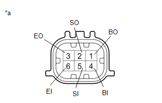 |
|
*a | Component without harness connected
(Rear Corner Ultrasonic Sensor RH) | | |
| NG |
| REPLACE REAR CORNER ULTRASONIC SENSOR RH |
|
OK | |
| |
| 8. |
INSPECT REAR CENTER ULTRASONIC SENSOR RH |
| (a) Measure the resistance according to the value(s) in the table below.
Standard Resistance: |
Tester Connection | Condition |
Specified Condition | |
4 (BI) - 6 (EI) | Always |
10 kΩ or higher | |
4 (BI) - 1 (BO) | Always |
Below 1 Ω | |
5 (SI) - 2 (SO) | Always |
Below 30 Ω | |
6 (EI) - 3 (EO) | Always |
Below 1 Ω | | |
|
|
*a | Component without harness connected
(Rear Center Ultrasonic Sensor RH) | | |
| NG |
| REPLACE REAR CENTER ULTRASONIC SENSOR RH |
|
OK | |
| |
| 9. |
INSPECT REAR CENTER ULTRASONIC SENSOR LH |
| (a) Measure the resistance according to the value(s) in the table below.
Standard Resistance: |
Tester Connection | Condition |
Specified Condition | |
4 (BI) - 6 (EI) | Always |
10 kΩ or higher | |
4 (BI) - 1 (BO) | Always |
Below 1 Ω | |
5 (SI) - 2 (SO) | Always |
Below 30 Ω | |
6 (EI) - 3 (EO) | Always |
Below 1 Ω | | |
|
|
*a | Component without harness connected
(Rear Center Ultrasonic Sensor LH) | | |
| NG |
| REPLACE REAR CENTER ULTRASONIC SENSOR LH |
|
OK | |
| |
| 10. |
INSPECT REAR CORNER ULTRASONIC SENSOR LH |
| (a) Measure the resistance according to the value(s) in the table below.
Standard Resistance: |
Tester Connection | Condition |
Specified Condition | |
4 (BI) - 6 (EI) | Always |
10 kΩ or higher | |
4 (BI) - 1 | Always |
Below 1 Ω | |
5 (SI) - 2 | Always |
Below 30 Ω | |
6 (EI) - 3 | Always |
Below 1 Ω | |
 |
|
*a | Component without harness connected
(Rear Corner Ultrasonic Sensor LH) | | |
| NG |
| REPLACE REAR CORNER ULTRASONIC SENSOR LH |
|
OK | |
| |
| 11. |
REPLACE REAR CORNER ULTRASONIC SENSOR RH |
Click here
|
NEXT | |
| |
| 12. |
CHECK DTC OUTPUT (C1AED) |
(a) Clear the DTCs.
Body Electrical > Advanced Parking Guidance/ICS/Intuitive P/A > Clear DTCs
(b) Check for DTCs.
Body Electrical > Advanced Parking Guidance/ICS/Intuitive P/A > Trouble Codes
|
Result | Proceed to |
|
DTC C1AED is output | A |
|
No DTCs are output | B |
| B |
| END (REAR CORNER ULTRASONIC SENSOR RH WAS DEFECTIVE) |
|
A | |
| |
| 13. |
REPLACE REAR CENTER ULTRASONIC SENSOR RH |
Click here
|
NEXT | |
| |
| 14. |
CHECK DTC OUTPUT (C1AED) |
(a) Clear the DTCs.
Body Electrical > Advanced Parking Guidance/ICS/Intuitive P/A > Clear DTCs
(b) Check for DTCs.
Body Electrical > Advanced Parking Guidance/ICS/Intuitive P/A > Trouble Codes
|
Result | Proceed to |
|
DTC C1AED is output | A |
|
No DTCs are output | B |
| B |
| END (REAR CENTER ULTRASONIC SENSOR RH WAS DEFECTIVE) |
|
A | |
| |
| 15. |
REPLACE REAR CENTER ULTRASONIC SENSOR LH |
Click here
|
NEXT | |
| |
| 16. |
CHECK DTC OUTPUT (C1AED) |
(a) Clear the DTCs.
Body Electrical > Advanced Parking Guidance/ICS/Intuitive P/A > Clear DTCs
(b) Check for DTCs.
Body Electrical > Advanced Parking Guidance/ICS/Intuitive P/A > Trouble Codes
|
Result | Proceed to |
|
DTC C1AED is output | A |
|
No DTCs are output | B |
| B |
| END (REAR CENTER ULTRASONIC SENSOR LH WAS DEFECTIVE) |
|
A | |
| |
| 17. |
REPLACE REAR CORNER ULTRASONIC SENSOR LH |
Click here
|
NEXT | |
| |
| 18. |
CHECK DTC OUTPUT (C1AED) |
(a) Clear the DTCs.
Body Electrical > Advanced Parking Guidance/ICS/Intuitive P/A > Clear DTCs
(b) Check for DTCs.
Body Electrical > Advanced Parking Guidance/ICS/Intuitive P/A > Trouble Codes
|
Result | Proceed to |
|
DTC C1AED is output | A |
|
No DTCs are output | B |
| A |
| REPLACE CLEARANCE WARNING ECU ASSEMBLY |
| B |
| END (REAR CORNER ULTRASONIC SENSOR LH WAS DEFECTIVE) |
Calibration
CALIBRATION
NOTICE:
When
any of the following parts have been replaced, perform adjustment shown
in the following table. If not, the intuitive parking assist system may
not operate correctly.
ADJUST INTUITVE PARKING ASSIST SYSTEM
(a)
The necessary procedures (adjustment, calibration, initialization or
registration) that must be performed after parts are removed and
installed, or replaced during intuitive parking assist-sensor system
removal/installation are shown below.
|
Part Name | Operation |
Adjustment Item | Proceed to |
|
Clearance warning ECU assembly |
Replacement | Registration of bumper type |
 |
|
Steering angle neutral point* |
|
Bumper type registration |
|
Ultrasonic sensor detection angle registration |
|
Ultrasonic sensor |
- Removal and installation
- Replacement
| Measurement of Ultrasonic sensor detection angle |
|
Ultrasonic sensor detection angle registration |
|
An ultrasonic sensor becomes misaligned |
Measurement of Ultrasonic sensor detection angle |
|
Ultrasonic sensor detection angle registration |
|
An ultrasonic sensor is subjected to impact |
Measurement of Ultrasonic sensor detection angle |
|
Ultrasonic sensor detection angle registration |
- *: The steering sensor zero point can also be calibrated by driving the vehicle.
Click here
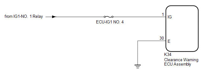
Clearance Warning ECU Power Source Circuit
DESCRIPTION
This circuit provides power to operate the clearance warning ECU assembly.
WIRING DIAGRAM
CAUTION / NOTICE / HINT
NOTICE:
Inspect the fuses for circuits related to this system before performing the following procedure.
PROCEDURE
| 1. |
CHECK HARNESS AND CONNECTOR (CLEARANCE WARNING ECU ASSEMBLY POWER SOURCE) |
(a) Disconnect the K34 clearance warning ECU assembly connector.
(b) Measure the voltage according to the value(s) in the table below.
Standard Voltage:
|
Tester Connection | Condition |
Specified Condition |
|
K34-1 (IG) - Body ground |
Engine switch on (IG) |
11 to 14 V |
|
K34-1 (IG) - Body ground |
Engine switch off | Below 1 V |
| NG |
 | REPAIR OR REPLACE HARNESS OR CONNECTOR |
|
OK |
 | |
| 2. |
CHECK HARNESS AND CONNECTOR (CLEARANCE WARNING ECU ASSEMBLY - BODY GROUND) |
(a) Measure the resistance according to the value(s) in the table below.
Standard Resistance:
|
Tester Connection | Condition |
Specified Condition |
|
K34-30 (E) - Body ground |
Always | Below 1 Ω |
| OK |
| PROCEED TO NEXT SUSPECTED AREA SHOWN IN PROBLEM SYMPTOMS TABLE |
| NG |
| REPAIR OR REPLACE HARNESS OR CONNECTOR |
Customize Parameters
CUSTOMIZE PARAMETERS
CUSTOMIZE INTUITIVE PARKING ASSIST SYSTEM
(a) Customizing with the Techstream.
NOTICE:
- When the customer requests a change in a function, first make sure that the function can be customized.
- Be sure to make a note of the current settings before customizing.
- When troubleshooting a function, first make sure that the function is set to the default setting.
(1) Connect the Techstream to the DLC3.
(2) Turn the engine switch on (IG).
(3) Turn the intuitive parking assist system on.
(4) Turn the Techstream on.
(5) Enter the following menus: Body Electrical / Advanced Parking Guidance/ICS/Intuitive P/A / Utility / Customize Setting.
(6) Select the setting by referring to the table below.
Warning
|
Tester Display | Description |
Default | Setting |
ECU |
| Fr Corner Sensor Onset Range |
Sets the detection operation range for the front corner sensors. |
Long | 0:Short,1:Long |
Clearance warning ECU assembly |
|
Rr Corner Sensor Onset Range |
Sets the detection operation range for the front corner sensors. |
Long | 0:Short,1:Long |
Clearance warning ECU assembly |
|
Fr Sensor Onset Range | Sets the detection operation range for the front center sensors. |
Wide | 0:Narrow,1:Wide |
Clearance warning ECU assembly |
|
Rr Sensor Onset Range | Sets the detection operation range for the rear center sensors. |
Wide | 0:Narrow,1:Wide |
Clearance warning ECU assembly |
|
Keep Sense Buzzer | Sets
whether the buzzer stops sounding when the distance between the vehicle
and a detected object does not change for 3 seconds. |
Avail | 0:Not Avail,1:Avail |
Clearance warning ECU assembly |
|
Fr & Rr Buzzer Volume |
Changes the buzzer volume setting. |
M2 | 001:L,010:M1,011:M2,100:M3,101:H |
Clearance warning ECU assembly |
|
Object Not Moving 3s Buzz Vol |
Sets
the volume at which the buzzer sounds when the distance between the
vehicle and a detected object does not change for 3 seconds. |
Keep | 00:Keep Vol,01:L,10:M1,11:M2 |
Clearance warning ECU assembly |
|
Leave Buzzer Volume | Sets the volume of the buzzer with respect to the distance between the vehicle and a detected object. |
L | 00:Keep Vol,01:L,10:M1,11:M2 |
Clearance warning ECU assembly |
|
Temporary Mute Reset Speed Adjust |
Sets the vehicle speed at which the temporary mute function resets. |
20 km/h | 00:System Link,01:15km/h,10:20km/h,11:30km/h |
Clearance warning ECU assembly |
|
Temporary Mute Function |
Sets the availability of the temporary mute function. |
ON | 0:OFF,1:ON |
Clearance warning ECU assembly |
Sensor
|
Tester Display | Description |
Default | Setting |
ECU |
| Sensor Condition N |
Makes the front sensors available when the shift lever is in N. |
Avail | 0:Not Avail,1:Avail |
Clearance warning ECU assembly |
Display
|
Tester Display | Description |
Default | Setting |
ECU |
| Approach Display OFF |
Sets whether the display turns off after an obstacle is no longer detected. |
Avail | 0:Not Avail,1:Avail |
Clearance warning ECU assembly |
|
Display Mode | The display mode setting (when the intuitive parking assist system is normal). |
All | 01:All,11:Undisp |
Clearance warning ECU assembly |
Data List / Active Test
DATA LIST / ACTIVE TEST
DATA LIST
NOTICE:
In
the table below, the values listed under "Normal Condition" are
reference values. Do not depend solely on these reference values when
deciding whether a part is faulty or not.
HINT:
Using
the Techstream to read the Data List allows the values or states of
switches, sensors, actuators and other items to be read without removing
any parts. This non-intrusive inspection can be very useful because
intermittent conditions or signals may be discovered before parts or
wiring is disturbed. Reading the Data List information early in
troubleshooting is one way to save diagnostic time.
(a) Connect the Techstream to the DLC3.
(b) Turn the engine switch on (IG).
(c) Turn the Techstream on.
(d) Enter the following menus: Body Electrical / Advanced Parking Guidance/ICS/Intuitive P/A / Data List.
(e) Read the Data List according to the display on the Techstream.
Body Electrical > Advanced Parking Guidance/ICS/Intuitive P/A > Data List
|
Tester Display | Measurement Item |
Range | Normal Condition |
Diagnostic Note |
|
Main Switch | Intuitive parking assist system switch assembly (Multi-information switch) |
OFF or ON | OFF: Intuitive parking assist system off
ON: Intuitive parking assist system on |
- |
| Intuitive P/A ECU Type |
Type of intuitive P/A ECU |
Normal | Normal: Normal clearance sonar type |
- |
| Fr Left Sensor |
Front left sensor information |
Undetect, Close R, Mid Y, Mid L Y, Freeze, Open or Blink |
Undetect: Not detected Close R: Detected (Close-range) [Red]
Mid Y: Detected (Medium-range) [Yellow] Mid L Y: Detected (Long-range) [Yellow]
Freeze: Sensor frozen Open: Open in sensor Blink: All displays blinking |
- |
| Fr Left Center Sensor |
Front left center sensor information |
Undetect, Close R, Mid Y, Mid L Y, Long Y, Freeze, Open or Blink |
Undetect: Not detected Close R: Detected (Close-range) [Red]
Mid Y: Detected (Medium-range) [Yellow] Mid L Y: Detected (Long-range) [Yellow]
Long Y: Detected (Longest-range) [Yellow] Freeze: Sensor frozen
Open: Open in sensor Blink: All displays blinking |
- |
| Fr Right Center Sensor |
Front right center sensor information |
Undetect, Close R, Mid Y, Mid L Y, Long Y, Freeze, Open or Blink |
Undetect: Not detected Close R: Detected (Close-range) [Red]
Mid Y: Detected (Medium-range) [Yellow] Mid L Y: Detected (Long-range) [Yellow]
Long Y: Detected (Longest-range) [Yellow] Freeze: Sensor frozen
Open: Open in sensor Blink: All displays blinking |
- |
| Fr Right Sensor |
Front right sensor information |
Undetect, Close R, Mid Y, Mid L Y, Freeze, Open or Blink |
Undetect: Not detected Close R: Detected (Close-range) [Red]
Mid Y: Detected (Medium-range) [Yellow] Mid L Y: Detected (Long-range) [Yellow]
Freeze: Sensor frozen Open: Open in sensor Blink: All displays blinking |
- |
| Rr Left Sensor |
Rear left sensor information |
Undetect, Close R, Mid Y, Mid L Y, Freeze, Open or Blink |
Undetect: Not detected Close R: Detected (Close-range) [Red]
Mid Y: Detected (Medium-range) [Yellow] Mid L Y: Detected (Long-range) [Yellow]
Freeze: Sensor frozen Open: Open in sensor Blink: All displays blinking |
- |
| Rr Left Center Sensor |
Rear left center sensor information |
Undetect, Close R, Mid Y, Mid L Y, Long Y, Freeze, Open or Blink |
Undetect: Not detected Close R: Detected (Close-range) [Red]
Mid Y: Detected (Medium-range) [Yellow] Mid L Y: Detected (Long-range) [Yellow]
Long Y: Detected (Longest-range) [Yellow] Freeze: Sensor frozen
Open: Open in sensor Blink: All displays blinking |
- |
| Rr Right Center Sensor |
Rear right center sensor information |
Undetect, Close R, Mid Y, Mid L Y, Long Y, Freeze, Open or Blink |
Undetect: Not detected Close R: Detected (Close-range) [Red]
Mid Y: Detected (Medium-range) [Yellow] Mid L Y: Detected (Long-range) [Yellow]
Long Y: Detected (Longest-range) [Yellow] Freeze: Sensor frozen
Open: Open in sensor Blink: All displays blinking |
- |
| Rr Right Sensor |
Rear right sensor information |
Undetect, Close R, Mid Y, Mid L Y, Freeze, Open or Blink |
Undetect: Not detected Close R: Detected (Close-range) [Red]
Mid Y: Detected (Medium-range) [Yellow] Mid L Y: Detected (Long-range) [Yellow]
Freeze: Sensor frozen Open: Open in sensor Blink: All displays blinking |
- |
| Fr Sensor Onset Range |
Detection operation range (for front center sensors) |
Narrow or Wide | Narrow: 600 mm (23.6 in.)
Wide: 1000 mm (39.4 in.) |
Customized value displayed |
|
Rr Sensor Onset Range | Detection operation range (for rear center sensors) |
Narrow or Wide | Narrow: 600 mm (23.6 in.)
Wide: 1500 mm (59.1 in.) |
Customized value displayed |
|
Keep Sense Buzzer | Keep sense buzzer operation |
Not Avail or Avail | Not Avail: Buzzer stops
Avail: Buzzer sounds continuously |
Customized value displayed |
|
Fr & Rr Buzzer Volume |
Buzzer volume setting | L, M or H |
L: Low volume M: Medium volume H: High volume |
Customized value displayed |
|
Sensor Condition N | Front sensor operation |
Not Avail or Avail | Not Avail: Front sensors not available
Avail: Front sensors available |
Customized value displayed |
|
Approach Display OFF | Whether the display turns off after an obstacle is no longer detected. |
Not Avail or Avail | Not Avail: Not displayed
Avail: Displayed | Customized value displayed |
|
Object Not Moving 3s Buzz Vol |
The volume at which the buzzer sounds when the distance between the vehicle and a detected object does not change for 3 seconds. |
Keep Vol, L, M1 or M2 | Keep Vol: Keep volume
L: High M1: Medium M2: Medium low |
Customized value displayed |
|
Leave Buzzer Volume | The volume of the buzzer with respect to the distance between the vehicle and a detected object. |
Keep Vol, L, M1 or M2 | Keep Vol: Keep volume
L: High M1: Medium M2: Medium low |
Customized value displayed |
|
Fr Corner Sensor Onset Range |
Detection operation range (for front corner sensors) |
Short or Long | Short: 450 mm (17.7 in.)
Long: 600 mm (23.6 in.) |
Customized value displayed |
|
Rr Corner Sensor Onset Range |
Detection operation range (for rear corner sensors) |
Short or Long | Short: 450 mm (17.7 in.)
Long: 600 mm (23.6 in.) |
Customized value displayed |
|
Temporary Mute Reset Speed Adjust |
Temporary mute reset speed adjustment setting |
System Link, 15 km/h, 20 km/h or 30 km/h |
System Link: Adjustment will not be canceled due to vehicle speed
15 km/h: Adjustment will be canceled when vehicle speed reaches 15 km/h
20 km/h: Adjustment will be canceled when vehicle speed reaches 20 km/h
30 km/h: Adjustment will be canceled when vehicle speed reaches 30 km/h |
Customized value displayed |
|
Temporary Mute Function |
Temporary mute function setting |
OFF or ON | OFF: Temporary Mute Function not operating
ON: Temporary Mute Function operating |
Customized value displayed |
|
Advanced Parking Guidance System |
Existence of advanced parking guidance system |
Without, With or Unfixed |
Without: w/o Advanced parking guidance system With: w/ Advanced parking guidance system
Unfixed: Unknown | - |
|
Parking Signal | Parking signal |
OFF or ON | OFF: Shift lever in any position other than P
ON: Shift lever in P |
- |
| Reverse Signal |
Reverse signal | OFF or ON |
OFF: Shift lever not in R ON: Shift lever in R |
- |
| Intuitive P/A ECU |
Clearance warning ECU assembly information |
Normal or Abnormal | Normal: Clearance warning ECU assembly normal
Abnormal: Clearance warning ECU assembly not normal |
- |
| Rr Right Freezed History |
Rear right sensor frozen history |
Not Rec or Recorded | Not Rec: No record history
Recorded: Record history |
- |
| Rr Right Center Freezed History |
Rear right center sensor frozen history |
Not Rec or Recorded | Not Rec: No record history
Recorded: Record history |
- |
| Rr Left Center Freezed History |
Rear left center sensor frozen history |
Not Rec or Recorded | Not Rec: No record history
Recorded: Record history |
- |
| Rr Left Freezed History |
Rear left sensor frozen history |
Not Rec or Recorded | Not Rec: No record history
Recorded: Record history |
- |
| Fr Right Freezed History |
Front right sensor frozen history |
Not Rec or Recorded | Not Rec: No record history
Recorded: Record history |
- |
| Fr Right Center Freezed History |
Front right center sensor frozen history |
Not Rec or Recorded | Not Rec: No record history
Recorded: Record history |
- |
| Fr Left Center Freezed History |
Front left center sensor frozen history |
Not Rec or Recorded | Not Rec: No record history
Recorded: Record history |
- |
| Fr Left Freezed History |
Front left sensor frozen history |
Not Rec or Recorded | Not Rec: No record history
Recorded: Record history |
- |
| Steering Wheel Location |
Location of the steering wheel |
Right, Left or Unfixed |
Right: RH side Left: LH side Unfixed: Unknown |
- |
| HV System |
Existence of hybrid system |
Without, With or Unfixed |
Without: w/o Hybrid system With: w/ Hybrid system Unfixed: Unknown |
- |
| Rear Right Sensor Dirty |
Rear right sensor dirt history |
Not Rec or Recorded | Not Rec: No record history
Recorded: Record history |
- |
| Rear Right Center Sensor Dirty |
Rear right center sensor dirt history |
Not Rec or Recorded | Not Rec: No record history
Recorded: Record history |
- |
| Rear Left Center Sensor Dirty |
Rear left center sensor dirt history |
Not Rec or Recorded | Not Rec: No record history
Recorded: Record history |
- |
| Rear Left Sensor Dirty |
Rear left sensor dirt history |
Not Rec or Recorded | Not Rec: No record history
Recorded: Record history |
- |
| Front Right Sensor Dirty |
Front right sensor dirt history |
Not Rec or Recorded | Not Rec: No record history
Recorded: Record history |
- |
| Front Right Center Sensor Dirty |
Front right center sensor dirt history |
Not Rec or Recorded | Not Rec: No record history
Recorded: Record history |
- |
| Front Left Center Sensor Dirty |
Front left center sensor dirt history |
Not Rec or Recorded | Not Rec: No record history
Recorded: Record history |
- |
| Front Left Sensor Dirty |
Front left sensor dirt history |
Not Rec or Recorded | Not Rec: No record history
Recorded: Record history |
- |
| ICS System |
Existence of intelligent clearance sonar system |
Without or With | Without: w/o Intelligent clearance sonar system
With: w/ Intelligent clearance sonar system |
- |
| # Codes |
Number of stored DTCs | min.: 0, max.: 255 |
Number of DTCs will be displayed |
- |
ACTIVE TEST
HINT:
Using
the Techstream to perform Active Tests allows relays, VSVs, actuators
and other items to be operated without removing any parts. This
non-intrusive functional inspection can be very useful because
intermittent operation may be discovered before parts or wiring is
disturbed. Performing Active Tests early in troubleshooting is one way
to save diagnostic time. Data List information can be displayed while
performing Active Tests.
(a) Connect the Techstream to the DLC3.
(b) Turn the engine switch on (IG).
(c) Turn the Techstream on.
(d) Enter the following menus: Body Electrical / Advanced Parking Guidance/ICS/Intuitive P/A / Active Test.
(e) According to the display on the Techstream, perform the Active Test.
Body Electrical > Advanced Parking Guidance/ICS/Intuitive P/A > Active Test
|
Tester Display | Measurement Item |
Control Range | Diagnostic Note |
|
Front Buzzer | No. 1 clearance warning buzzer |
Stop or Operate | Confirm that the vehicle is stopped and the engine switch is on (IG) |
|
Rear Buzzer | No. 2 clearance warning buzzer |
Stop or Operate | Confirm that the vehicle is stopped and the engine switch is on (IG) |
Diagnosis System
DIAGNOSIS SYSTEM
DESCRIPTION
(a)
When troubleshooting a vehicle with a diagnosis system, the only
difference from the usual troubleshooting procedure is connecting the
Techstream to the vehicle and reading various data output from the
clearance warning ECU assembly.
The clearance warning ECU assembly stores DTCs when the ECU detects a malfunction in the ECU itself or in its circuits.
To
check the DTCs, connect the Techstream to the DLC3 on the vehicle. The
Techstream makes it possible to clear the DTCs, activate the various
actuators, and check the freeze frame data and Data List.
CHECK DLC3
(a) Check the DLC3.
Click here 
Diagnostic Trouble Code Chart
DIAGNOSTIC TROUBLE CODE CHART
Intuitive Parking Assist System |
DTC No. | Detection Item |
Link |
| C1AE1 |
Front Left Sensor Malfunction |
 |
|
C1AE2 | Front Left Center Sensor |
|
|
C1AE3 | Front Right Center Sensor |
|
|
C1AE4 | Front Right Sensor Malfunction |
|
|
C1AE6 | Rear Left Sensor Malfunction |
|
|
C1AE7 | Rear Left Center Sensor Malfunction |
|
|
C1AE8 | Rear Right Center Sensor Malfunction |
|
|
C1AE9 | Rear Right Sensor Malfunction |
|
|
C1AEC | Front Sensor Communication Malfunction |
|
|
C1AED | Rear Sensor Communication Malfunction |
|
|
U0073 | Control Module Communication Bus "A" Off |
|
|
U0155 | Lost Communication with Instrument Panel Cluster (IPC) Control Module |
|
|
U1000 | CAN Communication Failure (Message Registry) |
|
Dtc Check / Clear
DTC CHECK / CLEAR
CHECK DTC
(a) Connect the Techstream to the DLC3.
(b) Turn the engine switch on (IG).
(c) Turn the intuitive parking assist system on.
(d) Turn the Techstream on.
(e) Enter the following menus: Body Electrical / Advanced Parking Guidance/ICS/Intuitive P/A / Trouble Codes.
(f) Check for DTCs.
Body Electrical > Advanced Parking Guidance/ICS/Intuitive P/A > Trouble Codes
CLEAR DTC
(a) Connect the Techstream to the DLC3.
(b) Turn the engine switch on (IG).
(c) Turn the intuitive parking assist system on.
(d) Turn the Techstream on.
(e) Enter the following menus: Body Electrical / Advanced Parking Guidance/ICS/Intuitive P/A / Trouble Codes.
(f) Clear the DTCs.
Body Electrical > Advanced Parking Guidance/ICS/Intuitive P/A > Clear DTCsHow To Proceed With Troubleshooting
CAUTION / NOTICE / HINT
HINT:
- Use the following procedure to troubleshoot the intuitive parking assist system.
- *: Use the Techstream.
PROCEDURE
|
1. | VEHICLE BROUGHT TO WORKSHOP |
|
NEXT |
 | |
| 2. |
CUSTOMER PROBLEM ANALYSIS |
|
NEXT | |
| |
| 3. |
INSPECT BATTERY VOLTAGE |
(a) Measure the battery voltage.
Standard Voltage:
11 to 14 V
If the voltage is below 11 V, replace or recharge the battery before proceeding to the next step.
|
NEXT | |
| |
| 4. |
CHECK CAN COMMUNICATION SYSTEM* |
(a) Use the Techstream to check if the CAN communication system is functioning normally.
Click here 
|
Result | Proceed to |
|
CAN communication system DTCs are not output |
A |
| CAN communication system DTCs are output |
B |
| B |
 | GO TO CAN COMMUNICATION SYSTEM |
|
A | |
| |
| 5. |
PROBLEM SYMPTOM CONFIRMATION |
|
NEXT | |
| |
(a) Check for DTCs.
Click here
Body Electrical > Advanced Parking Guidance/ICS/Intuitive P/A > Trouble Codes
|
Result | Proceed to |
|
DTCs are output | A |
|
DTCs are not output (Problem symptom does not occur) |
B |
| DTCs are not output (Problem symptom occurs) |
C |
| B |
| GO TO STEP 8 |
| C |
| GO TO STEP 9 |
|
A | |
| |
| 7. |
DIAGNOSTIC TROUBLE CODE CHART (INTUITIVE PARKING ASSIST SYSTEM) |
(a) Refer to Diagnostic Trouble Code Chart.
Click here
NOTICE:
The
clearance warning ECU assembly outputs DTCs for the following system.
When DTCs other than those in Diagnostic Trouble Code Chart for the
intuitive parking assist system are output, refer to Diagnostic Trouble
Code Chart for the relevant systems.
|
System | Proceed to |
|
Intelligent Clearance Sonar System |
|
| NEXT |
| GO TO STEP 11 |
(a) Refer to Symptom Simulation.
Click here
|
NEXT | |
| |
| 9. |
PROBLEM SYMPTOMS TABLE |
(a) Refer to Problem Symptoms Table.
Click here
|
Result | Proceed to |
|
Fault is not listed in Problem Symptoms Table |
A |
| Fault is listed in Problem Symptoms Table |
B |
| B |
| GO TO STEP 11 |
|
A | |
| |
| 10. |
OVERALL ANALYSIS AND TROUBLESHOOTING |
(a) Operation Check
Click here
(b) Terminals of ECU
Click here
(c) Data List / Active Test
Click here
|
NEXT | |
| |
|
NEXT | |
| |
| 12. |
IDENTIFICATION OF PROBLEM |
|
NEXT | |
| |
|
NEXT | |
| |
| NEXT |
| END |
No. 1 Clearance Warning Buzzer Circuit
DESCRIPTION
This circuit
consists of the No. 1 clearance warning buzzer and clearance warning ECU
assembly. An ECU-excited type buzzer is used. The ECU operates the
buzzers using a sound pattern that changes depending on the distance to
the obstacle.
WIRING DIAGRAM

PROCEDURE
| 1. |
PERFORM ACTIVE TEST USING TECHSTREAM (FRONT BUZZER) |
(a) Connect the Techstream to the DLC3.
(b) Turn the engine switch on (IG).
(c) Turn the Techstream on.
(d) Enter the following menus: Body Electrical / Advanced Parking Guidance/ICS/Intuitive P/A / Active Test.
(e) Check that the front buzzer operates by performing the Active Test.
Body Electrical > Advanced Parking Guidance/ICS/Intuitive P/A > Active Test
|
Tester Display | Measurement Item |
Control Range | Diagnostic Note |
|
Front Buzzer | No. 1 clearance warning buzzer |
Stop or Operate | Confirm that the vehicle is stopped and the engine switch is on (IG) |
Body Electrical > Advanced Parking Guidance/ICS/Intuitive P/A > Active Test
|
Tester Display |
| Front Buzzer |
OK:
The No. 1 clearance warning buzzer sounds.
| OK |
 | PROCEED TO NEXT SUSPECTED AREA SHOWN IN PROBLEM SYMPTOMS TABLE |
|
NG |
 | |
| 2. |
CHECK HARNESS AND CONNECTOR (CLEARANCE WARNING ECU ASSEMBLY - NO. 1 CLEARANCE WARNING BUZZER) |
(a) Disconnect the K34 clearance warning ECU assembly connector.
(b) Disconnect the G51 No. 1 clearance warning buzzer connector.
(c) Measure the resistance according to the value(s) in the table below.
Standard Resistance:
|
Tester Connection | Condition |
Specified Condition |
|
K34-14 (CBZ) - G51-1 (Z+) |
Always | Below 1 Ω |
|
K34-13 (EF) - G51-2 (Z-) |
Always | Below 1 Ω |
|
K34-14 (CBZ) or G51-1 (Z+) - Body ground |
Always | 10 kΩ or higher |
|
K34-13 (EF) or G51-2 (Z-) - Body ground |
Always | 10 kΩ or higher |
| NG |
| REPAIR OR REPLACE HARNESS OR CONNECTOR |
|
OK | |
| |
| 3. |
REPLACE NO. 1 CLEARANCE WARNING BUZZER |
(a) Replace the No. 1 clearance warning buzzer with a new or known good one.
Click here 
|
NEXT | |
| |
| 4. |
PERFORM ACTIVE TEST USING TECHSTREAM (FRONT BUZZER) |
(a) Connect the Techstream to the DLC3.
(b) Turn the engine switch on (IG).
(c) Turn the Techstream on.
(d) Enter the following menus: Body Electrical / Advanced Parking Guidance/ICS/Intuitive P/A / Active Test.
(e) Check that the front buzzer operates by performing the Active Test.
Body Electrical > Advanced Parking Guidance/ICS/Intuitive P/A > Active Test
|
Tester Display | Measurement Item |
Control Range | Diagnostic Note |
|
Front Buzzer | No. 1 clearance warning buzzer |
Stop or Operate | Confirm that the vehicle is stopped and the engine switch is on (IG) |
Body Electrical > Advanced Parking Guidance/ICS/Intuitive P/A > Active Test
|
Tester Display |
| Front Buzzer |
OK:
The No. 1 clearance warning buzzer sounds.
| OK |
| END (NO. 1 CLEARANCE WARNING BUZZER WAS DEFECTIVE) |
| NG |
| REPLACE CLEARANCE WARNING ECU ASSEMBLY |
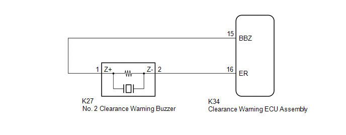
No. 2 Clearance Warning Buzzer Circuit
DESCRIPTION
This circuit
consists of the No. 2 clearance warning buzzer and clearance warning ECU
assembly. An ECU-excited type buzzer is used. The ECU operates the
buzzers using a sound pattern that changes depending on the distance to
the obstacle.
WIRING DIAGRAM
PROCEDURE
| 1. |
PERFORM ACTIVE TEST USING TECHSTREAM (REAR BUZZER) |
(a) Connect the Techstream to the DLC3.
(b) Turn the engine switch on (IG).
(c) Turn the Techstream on.
(d) Enter the following menus: Body Electrical / Advanced Parking Guidance/ICS/Intuitive P/A / Active Test.
(e) Check that the rear buzzer operates by performing the Active Test.
Body Electrical > Advanced Parking Guidance/ICS/Intuitive P/A > Active Test
|
Tester Display | Measurement Item |
Control Range | Diagnostic Note |
|
Rear Buzzer | No. 2 clearance warning buzzer |
Stop or Operate | Confirm that the vehicle is stopped and the engine switch is on (IG) |
Body Electrical > Advanced Parking Guidance/ICS/Intuitive P/A > Active Test
|
Tester Display |
| Rear Buzzer |
OK:
The No. 2 clearance warning buzzer sounds.
| OK |
 | PROCEED TO NEXT SUSPECTED AREA SHOWN IN PROBLEM SYMPTOMS TABLE |
|
NG |
 | |
| 2. |
CHECK HARNESS AND CONNECTOR (CLEARANCE WARNING ECU ASSEMBLY - NO. 2 CLEARANCE WARNING BUZZER) |
(a) Disconnect the K34 clearance warning ECU assembly connector.
(b) Disconnect the K27 No. 2 clearance warning buzzer connector.
(c) Measure the resistance according to the value(s) in the table below.
Standard Resistance:
|
Tester Connection | Condition |
Specified Condition |
|
K34-15 (BBZ) - K27-1 (Z+) |
Always | Below 1 Ω |
|
K34-16 (ER) - K27-2 (Z-) |
Always | Below 1 Ω |
|
K34-15 (BBZ) or K27-1 (Z+) - Body ground |
Always | 10 kΩ or higher |
|
K34-16 (ER) or K27-2 (Z-) - Body ground |
Always | 10 kΩ or higher |
| NG |
| REPAIR OR REPLACE HARNESS OR CONNECTOR |
|
OK | |
| |
| 3. |
REPLACE NO. 2 CLEARANCE WARNING BUZZER |
(a) Replace the No. 2 clearance warning buzzer with a new or known good one.
Click here 
|
NEXT | |
| |
| 4. |
PERFORM ACTIVE TEST USING TECHSTREAM (REAR BUZZER) |
(a) Connect the Techstream to the DLC3.
(b) Turn the engine switch on (IG).
(c) Turn the Techstream on.
(d) Enter the following menus: Body Electrical / Advanced Parking Guidance/ICS/Intuitive P/A / Active Test.
(e) Check that the rear buzzer operates by performing the Active Test.
Body Electrical > Advanced Parking Guidance/ICS/Intuitive P/A > Active Test
|
Tester Display | Measurement Item |
Control Range | Diagnostic Note |
|
Rear Buzzer | No. 2 clearance warning buzzer |
Stop or Operate | Confirm that the vehicle is stopped and the engine switch is on (IG) |
Body Electrical > Advanced Parking Guidance/ICS/Intuitive P/A > Active Test
|
Tester Display |
| Rear Buzzer |
OK:
The No. 2 clearance warning buzzer sounds.
| OK |
| END (NO. 2 CLEARANCE WARNING BUZZER WAS DEFECTIVE) |
| NG |
| REPLACE CLEARANCE WARNING ECU ASSEMBLY |
Operation Check
OPERATION CHECK
Self-diagnosis System
(a)
If the clearance warning ECU assembly detects that an ultrasonic sensor
is malfunctioning, a malfunction indication is displayed on the
combination meter assembly and combination meter assembly.
|
Malfunctioning Item | Detection Condition |
Warning Message (Multi-information Display) |
Buzzer Sounding (No. 1 Clearance Warning Buzzer and No. 2 Clearance Warning Buzzer) |
Suspected Area |
| Frozen indication |
- The ultrasonic sensor is covered with foreign matter, such as mud or snow
- The ultrasonic sensor is frozen
| Parking Assist Unavailable Clean Parking Assist Sensor |
â—‹ |
- Check if any foreign matter is attached to the ultrasonic sensors and their surrounding areas
Click here 
- If there is no foreign matter attached to the ultrasonic sensors and their surrounding areas, check for DTCs
Click here
|
| Open circuit indication |
- There is an open circuit between the clearance warning ECU assembly and the ultrasonic sensor
- The ultrasonic sensor is malfunctioning
| Parking Assist Malfunction Visit Your Dealer |
â—‹ | Check for DTCs Click here
|
|
Communication malfunction indication |
The ultrasonic sensor is malfunctioning |
Parking Assist Unavailable |
â—‹ | Check for DTCs
Click here |
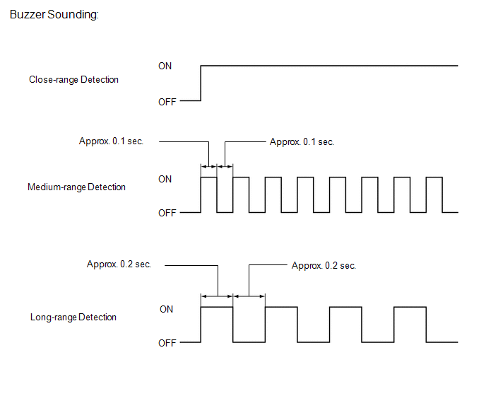
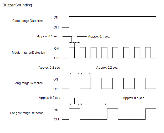
(1) Buzzer Sounding (No. 1 Clearance Warning Buzzer and No. 2 Clearance Warning Buzzer)
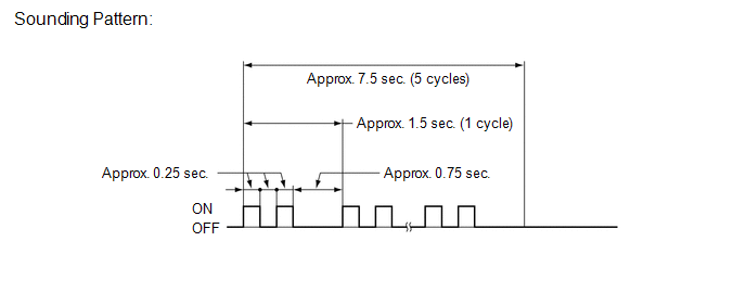
HINT:
Buzzer sounding is stopped after approximately 7.5 seconds elapsed.
DETECTION RANGE MEASUREMENT AND DISPLAY INSPECTION
NOTICE:
Perform
the following measurement and inspection with the shift lever in a
position other than P. Be sure to apply the parking brake and depress
the brake pedal firmly to prevent the vehicle from moving.
(a) Turn the engine switch on (IG).
(b) Turn the intuitive parking assist system on.
(c) Detection range measurement:
(1) Move the shift lever according to the table below.
|
Measurement Area | Shift Lever Position |
|
Front Corner | In any position other than P |
|
Front Center | In any position other than P or R |
|
Rear Corner |
R |
| Rear Center |
(2)
Move a 60 mm (2.4 in.) diameter pole near each sensor to measure its
detection range. When measuring the longest-range detection of the front
center sonar and the rear center sonar, use a wall or equivalent.
NOTICE:
These
detection ranges are applicable when positioning the 60 mm (2.4 in.)
diameter pole parallel or perpendicular to the ground. The detection
range varies depending on the measuring method and type of obstacle
(such as walls).
HINT:
Have an assistant move the pole.
Corner Sonar Detection Range
 Front Center Sonar Detection Range
 Rear Center Sonar Detection Range
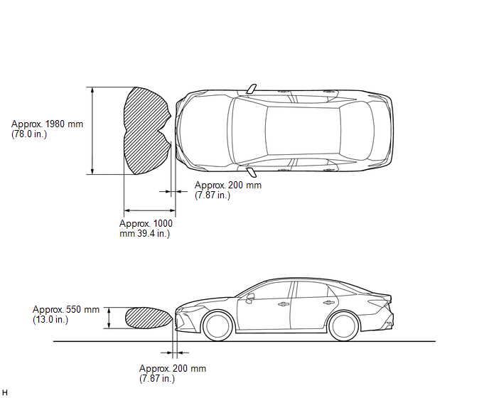
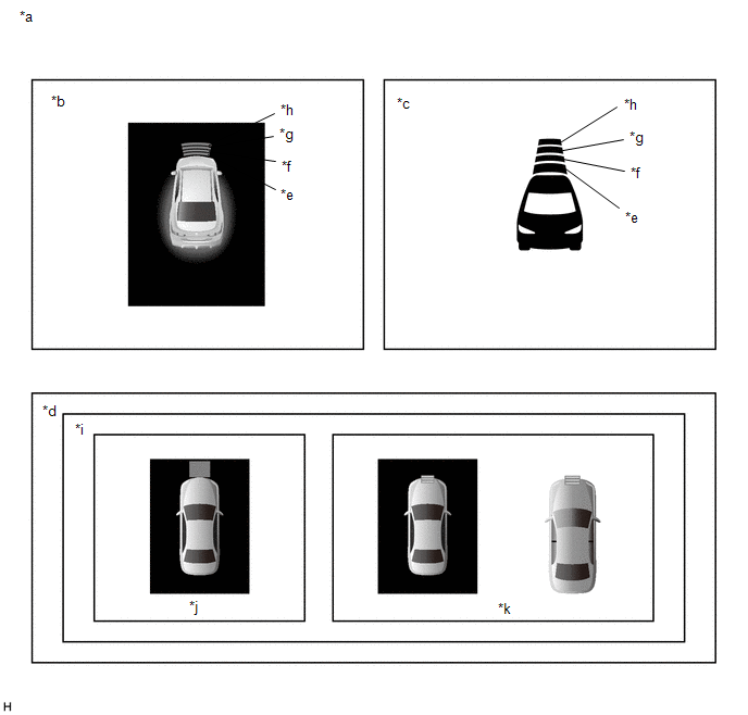
(d) Front corner sonar display and buzzer operation check
(1) When the front corner ultrasonic sensor have detected an obstacle, check the displays and check that the buzzer sounds.
Operation Condition |
Engine Switch | Intuitive Parking Assist System |
Shift Lever Position | Vehicle Speed |
|
On (IG) | On |
In any position other than P |
Less than approximately 10 km/h (6 mph) if speed is increasing |
|
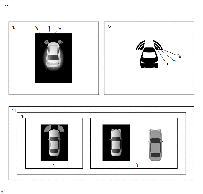
*a | Example (Front Corner Sonar) |
*b | Multi-information Display |
|
*c | Headup Display (w/ Headup Display System) |
*d | Multi-display |
|
*e | Close-range Detection |
*f | Medium-range Detection |
|
*g | Long-range Detection |
*h | Cooperated Display |
|
*i | w/ Parking Assist Monitor System |
*j | w/ Panoramic View Monitor System |
Standard:
Multi-information Display and Buzzer |
Detection Range | During Judgment |
Obstacle |
| Close-range detection
Within approx. 350 +/- 40 mm (13.8 +/- 1.57 in.) |
Buzzer: Sounds continuously Number of bars displayed: 1 (blinking) |
60 mm (2.4 in.) diameter pole |
|
Medium-range detection From approx. 350 +/- 40 to 450 +/- 50 mm (13.8 +/- 1.57 to 17.7 +/- 1.97 in.) |
Buzzer: Sounds intermittently (ON: 0.1 sec. / OFF: 0.1 sec.) Number of bars displayed: 2 (illuminated) |
60 mm (2.4 in.) diameter pole |
|
Long-range detection From approx. 450 +/- 50 to 800 +/- 80 mm (17.7 +/- 1.97 to 31.5 +/- 3.15 in.) |
Buzzer: Sounds intermittently (ON: 0.2 sec. / OFF: 0.2 sec.) Number of bars displayed: 3 (illuminated) |
60 mm (2.4 in.) diameter pole |
Headup Display and Buzzer (Cooperated Display (w/ Headup Display System)) |
Detection Range | During Judgment |
Obstacle |
| Close-range detection
Within approx. 350 +/- 40 mm (13.8 +/- 1.57 in.) |
Buzzer: Sounds continuously Number of bars displayed: 1 (blinking) |
60 mm (2.4 in.) diameter pole |
|
Medium-range detection From approx. 350 +/- 40 to 450 +/- 50 mm (13.8 +/- 1.57 to 17.7 +/- 1.97 in.) |
Buzzer: Sounds intermittently (ON: 0.1 sec. / OFF: 0.1 sec.) Number of bars displayed: 2 (illuminated) |
60 mm (2.4 in.) diameter pole |
|
Long-range detection From approx. 450 +/- 50 to 800 +/- 80 mm (17.7 +/- 1.97 to 31.5 +/- 3.15 in.) |
Buzzer: Sounds intermittently (ON: 0.2 sec. / OFF: 0.2 sec.) Number of bars displayed: 3 (illuminated) |
60 mm (2.4 in.) diameter pole |
Multi-display and Buzzer (Cooperated Display) |
Detection Range | During Judgment |
Obstacle |
| Close-range detection
Within approx. 350 +/- 40 mm (13.8 +/- 1.57 in.) |
Buzzer: Sounds continuously Color of bars displayed: Red (illuminated) |
60 mm (2.4 in.) diameter pole |
|
Medium-range detection From approx. 350 +/- 40 to 450 +/- 50 mm (13.8 +/- 1.57 to 17.7 +/- 1.97 in.) |
Buzzer: Sounds intermittently (ON: 0.1 sec. / OFF: 0.1 sec.) Color of bars displayed: Yellow (blinking) |
60 mm (2.4 in.) diameter pole |
|
Long-range detection From approx. 450 +/- 50 to 800 +/- 80 mm (17.7 +/- 1.97 to 31.5 +/- 3.15 in.) |
Buzzer: Sounds intermittently (ON: 0.2 sec. / OFF: 0.2 sec.) Color of bars displayed: Yellow (blinking) |
60 mm (2.4 in.) diameter pole |
HINT:
Ultrasonic
waves are used to measure the detection range; however, the detection
range may vary depending on the ambient temperature.
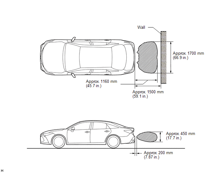
(e) Front center sonar display and buzzer operation check
(1) When the front center ultrasonic sensor have detected an obstacle, check the display and check that the buzzer sounds.
Operation Condition |
Engine Switch | Intuitive Parking Assist System |
Shift Lever Position | Vehicle Speed |
|
On (IG) | On |
In any position other than P or R |
Less than approximately 10 km/h (6 mph) if speed is increasing |
|
*a | Example (Front Center Sonar) |
*b | Multi-information Display |
|
*c | Headup Display (w/ Headup Display System) |
*d | Multi-display |
|
*e | Close-range Detection |
*f | Medium-range Detection |
|
*g | Long-range Detection |
*h | Longest-range Detection |
|
*i | Cooperated Display |
*j | w/ Parking Assist Monitor System |
|
*k | w/ Panoramic View Monitor System |
- | - |
Standard:
Multi-information Display and Buzzer |
Detection Range | During Detection |
Obstacle |
| Close-range detection
Within approx. 350 +/- 40 mm (13.8 +/- 1.57 in.) |
Buzzer: Sounds continuously Number of bars displayed: 1 (blinking) |
60 mm (2.4 in.) diameter pole |
|
Medium-range detection From approx. 350 +/- 40 to 450 +/- 50 mm (13.8 +/- 1.57 to 17.7 +/- 1.97 in.) |
Buzzer: Sounds intermittently (ON: 0.1 sec. / OFF: 0.1 sec.) Number of bars displayed: 2 (illuminated) |
60 mm (2.4 in.) diameter pole |
|
Long-range detection From approx. 450 +/- 50 to 730 +/- 60 mm (17.7 +/- 1.97 to 28.7 +/- 2.36 in.) |
Buzzer: Sounds intermittently (ON: 0.2 sec. / OFF: 0.2 sec.) Number of bars displayed: 3 (illuminated) |
60 mm (2.4 in.) diameter pole |
|
Longest-range detection From approx. 730 +/- 60 to 1000 +/- 100 mm (28.7 +/- 2.36 to 39.4 +/- 3.94 in.) |
Buzzer: Sounds intermittently (ON: 0.2 sec. / OFF: 0.5 sec.) Number of bars displayed: 4 (illuminated) |
Wall |
Headup Display and Buzzer (Cooperated Display (w/ Headup Display System)) |
Detection Range | During Detection |
Obstacle |
| Close-range detection
Within approx. 350 +/- 40 mm (13.8 +/- 1.57 in.) |
Buzzer: Sounds continuously Number of bars displayed: 1 (blinking) |
60 mm (2.4 in.) diameter pole |
|
Medium-range detection From approx. 350 +/- 40 to 450 +/- 50 mm (13.8 +/- 1.57 to 17.7 +/- 1.97 in.) |
Buzzer: Sounds intermittently (ON: 0.1 sec. / OFF: 0.1 sec.) Number of bars displayed: 2 (illuminated) |
60 mm (2.4 in.) diameter pole |
|
Long-range detection From approx. 450 +/- 50 to 730 +/- 60 mm (17.7 +/- 1.97 to 28.7 +/- 2.36 in.) |
Buzzer: Sounds intermittently (ON: 0.2 sec. / OFF: 0.2 sec.) Number of bars displayed: 3 (illuminated) |
60 mm (2.4 in.) diameter pole |
|
Longest-range detection From approx. 730 +/- 60 to 1000 +/- 100 mm (28.7 +/- 2.36 to 39.4 +/- 3.94 in.) |
Buzzer: Sounds intermittently (ON: 0.2 sec. / OFF: 0.5 sec.) Number of bars displayed: 4 (illuminated) |
Wall |
Multi-display and Buzzer (Cooperated Display) |
Detection Range | During Detection |
Obstacle |
| Close-range detection
Within approx. 350 +/- 40 mm (13.8 +/- 1.57 in.) |
Buzzer: Sounds continuously Color of bars displayed: Red (illuminated) |
60 mm (2.4 in.) diameter pole |
|
Medium-range detection From approx. 350 +/- 40 to 450 +/- 50 mm (13.8 +/- 1.57 to 17.7 +/- 1.97 in.) |
Buzzer: Sounds intermittently (ON: 0.1 sec. / OFF: 0.1 sec.) Color of bars displayed: Yellow (blinking) |
60 mm (2.4 in.) diameter pole |
|
Long-range detection From approx. 450 +/- 50 to 730 +/- 60 mm (17.7 +/- 1.97 to 28.7 +/- 2.36 in.) |
Buzzer: Sounds intermittently (ON: 0.2 sec. / OFF: 0.2 sec.) Color of bars displayed: Yellow (blinking) |
60 mm (2.4 in.) diameter pole |
|
Longest-range detection From approx. 730 +/- 60 to 1000 +/- 100 mm (28.7 +/- 2.36 to 39.4 +/- 3.94 in.) |
Buzzer: Sounds intermittently (ON: 0.2 sec. / OFF: 0.5 sec.) Color of bars displayed: Yellow (blinking) |
Wall |
HINT:
Ultrasonic
waves are used to measure the detection range; however, the detection
range may vary depending on the ambient temperature.
(f) Rear corner sonar display and buzzer operation check
(1) When the rear corner ultrasonic sensor have detected an obstacle, check the display and check that the buzzer sounds.
Operation Condition |
Engine Switch | Intuitive Parking Assist System |
Shift Lever Position | Vehicle Speed |
|
On (IG) | On |
R | Less than approximately 10 km/h (6 mph) if speed is increasing |
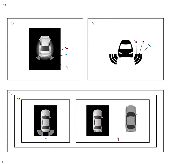
|
*a | Example (Rear Corner Sonar) |
*b | Multi-information Display |
|
*c | Headup Display (w/ Headup Display System) |
*d | Multi-display |
|
*e | Close-range Detection |
*f | Medium-range Detection |
|
*g | Long-range Detection |
*h | Cooperated Display |
|
*i | w/ Parking Assist Monitor System |
*j | w/ Panoramic View Monitor System |
Standard:
Multi-information Display and Buzzer |
Detection Range | During Judgment |
Obstacle |
| Close-range detection
Within approx. 350 +/- 40 mm (13.8 +/- 1.57 in.) |
Buzzer: Sounds continuously Number of bars displayed: 1 (blinking) |
60 mm (2.4 in.) diameter pole |
|
Medium-range detection From approx. 350 +/- 40 to 450 +/- 50 mm (13.8 +/- 1.57 to 17.7 +/- 1.97 in.) |
Buzzer: Sounds intermittently (ON: 0.1 sec. / OFF: 0.1 sec.) Number of bars displayed: 2 (illuminated) |
60 mm (2.4 in.) diameter pole |
|
Long-range detection From approx. 450 +/- 50 to 800 +/- 80 mm (17.7 +/- 1.97 to 31.5 +/- 3.15 in.) |
Buzzer: Sounds intermittently (ON: 0.2 sec. / OFF: 0.2 sec.) Number of bars displayed: 3 (illuminated) |
60 mm (2.4 in.) diameter pole |
Headup Display and Buzzer (Cooperated Display (w/ Headup Display System)) |
Detection Range | During Judgment |
Obstacle |
| Close-range detection
Within approx. 350 +/- 40 mm (13.8 +/- 1.57 in.) |
Buzzer: Sounds continuously Number of bars displayed: 1 (blinking) |
60 mm (2.4 in.) diameter pole |
|
Medium-range detection From approx. 350 +/- 40 to 450 +/- 50 mm (13.8 +/- 1.57 to 17.7 +/- 1.97 in.) |
Buzzer: Sounds intermittently (ON: 0.1 sec. / OFF: 0.1 sec.) Number of bars displayed: 2 (illuminated) |
60 mm (2.4 in.) diameter pole |
|
Long-range detection From approx. 450 +/- 50 to 800 +/- 80 mm (17.7 +/- 1.97 to 31.5 +/- 3.15 in.) |
Buzzer: Sounds intermittently (ON: 0.2 sec. / OFF: 0.2 sec.) Number of bars displayed: 3 (illuminated) |
60 mm (2.4 in.) diameter pole |
Multi-display and Buzzer (Cooperated Display) |
Detection Range | During Judgment |
Obstacle |
| Close-range detection
Within approx. 350 +/- 40 mm (13.8 +/- 1.57 in.) |
Buzzer: Sounds continuously Color of bars displayed: Red (illuminated) |
60 mm (2.4 in.) diameter pole |
|
Medium-range detection From approx. 350 +/- 40 to 450 +/- 50 mm (13.8 +/- 1.57 to 17.7 +/- 1.97 in.) |
Buzzer: Sounds intermittently (ON: 0.1 sec. / OFF: 0.1 sec.) Color of bars displayed: Yellow (blinking) |
60 mm (2.4 in.) diameter pole |
|
Long-range detection From approx. 450 +/- 50 to 800 +/- 80 mm (17.7 +/- 1.97 to 31.5 +/- 3.15 in.) |
Buzzer: Sounds intermittently (ON: 0.2 sec. / OFF: 0.2 sec.) Color of bars displayed: Yellow (blinking) |
60 mm (2.4 in.) diameter pole |
HINT:
Ultrasonic
waves are used to measure the detection range; however, the detection
range may vary depending on the ambient temperature.
(g) Rear center sonar display and buzzer operation check
(1) When the rear center ultrasonic sensor have detected an obstacle, check the display and check that the buzzer sounds.
Operation Condition |
Engine Switch | Intuitive Parking Assist System |
Shift Lever Position | Vehicle Speed |
|
On (IG) | On |
R | Less than approximately 10 km/h (6 mph) if speed is increasing |
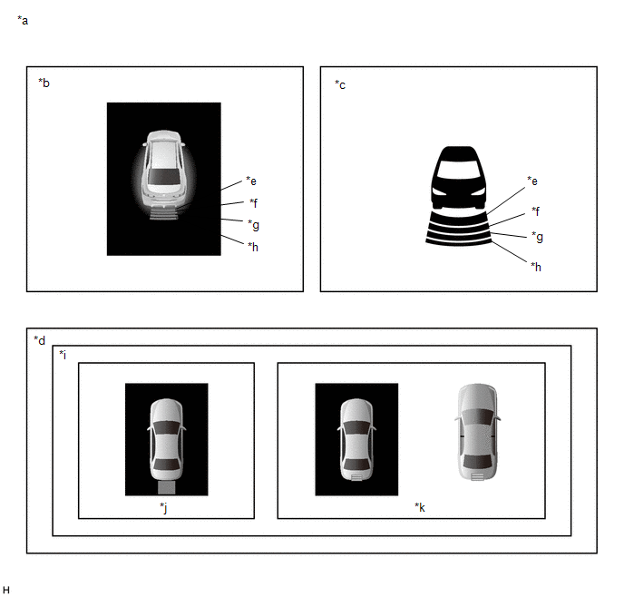
|
*a | Example (Rear Center Sonar) |
*b | Multi-information Display |
|
*c | Headup Display (w/ Headup Display System) |
*d | Multi-display |
|
*e | Close-range Detection |
*f | Medium-range Detection |
|
*g | Long-range Detection |
*h | Longest-range Detection |
|
*i | Cooperated Display |
*j | w/ Parking Assist Monitor System |
|
*k | w/ Panoramic View Monitor System |
- | - |
Standard:
Multi-information Display and Buzzer |
Detection Range | During Detection |
Obstacle |
| Close-range detection
Within approx. 350 +/- 40 mm (13.8 +/- 1.57 in.) |
Buzzer: Sounds continuously Number of bars displayed: 1 (blinking) |
60 mm (2.4 in.) diameter pole |
|
Medium-range detection From approx. 350 +/- 40 to 450 +/- 50 mm (13.8 +/- 1.57 to 17.7 +/- 1.97 in.) |
Buzzer: Sounds intermittently (ON: 0.1 sec. / OFF: 0.1 sec.) Number of bars displayed: 2 (illuminated) |
60 mm (2.4 in.) diameter pole |
|
Long-range detection From approx. 450 +/- 50 to 750 +/- 60 mm (17.7 +/- 1.97 to 29.5 +/- 2.36 in.) |
Buzzer: Sounds intermittently (ON: 0.2 sec. / OFF: 0.2 sec.) Number of bars displayed: 3 (illuminated) |
60 mm (2.4 in.) diameter pole |
|
Longest-range detection From approx. 750 +/- 60 to 1500 +/- 150 mm (29.5 +/- 2.36 to 59.1 +/- 5.91 in.) |
Buzzer: Sounds intermittently (ON: 0.2 sec. / OFF: 0.5 sec.) Number of bars displayed: 4 (illuminated) |
Wall |
Headup Display and Buzzer (Cooperated Display (w/ Headup Display System)) |
Detection Range | During Detection |
Obstacle |
| Close-range detection
Within approx. 350 +/- 40 mm (13.8 +/- 1.57 in.) |
Buzzer: Sounds continuously Number of bars displayed: 1 (blinking) |
60 mm (2.4 in.) diameter pole |
|
Medium-range detection From approx. 350 +/- 40 to 450 +/- 50 mm (13.8 +/- 1.57 to 17.7 +/- 1.97 in.) |
Buzzer: Sounds intermittently (ON: 0.1 sec. / OFF: 0.1 sec.) Number of bars displayed: 2 (illuminated) |
60 mm (2.4 in.) diameter pole |
|
Long-range detection From approx. 450 +/- 50 to 750 +/- 60 mm (17.7 +/- 1.97 to 29.5 +/- 2.36 in.) |
Buzzer: Sounds intermittently (ON: 0.2 sec. / OFF: 0.2 sec.) Number of bars displayed: 3 (illuminated) |
60 mm (2.4 in.) diameter pole |
|
Longest-range detection From approx. 750 +/- 60 to 1500 +/- 150 mm (29.5 +/- 2.36 to 59.1 +/- 5.91 in.) |
Buzzer: Sounds intermittently (ON: 0.2 sec. / OFF: 0.5 sec.) Number of bars displayed: 4 (illuminated) |
Wall |
Multi-display and Buzzer (Cooperated Display) |
Detection Range | During Detection |
Obstacle |
| Close-range detection
Within approx. 350 +/- 40 mm (13.8 +/- 1.57 in.) |
Buzzer: Sounds continuously Color of bars displayed: Red (illuminated) |
60 mm (2.4 in.) diameter pole |
|
Medium-range detection From approx. 350 +/- 40 to 450 +/- 50 mm (13.8 +/- 1.57 to 17.7 +/- 1.97 in.) |
Buzzer: Sounds intermittently (ON: 0.1 sec. / OFF: 0.1 sec.) Color of bars displayed: Yellow (blinking) |
60 mm (2.4 in.) diameter pole |
|
Long-range detection From approx. 450 +/- 50 to 750 +/- 60 mm (17.7 +/- 1.97 to 29.5 +/- 2.36 in.) |
Buzzer: Sounds intermittently (ON: 0.2 sec. / OFF: 0.2 sec.) Color of bars displayed: Yellow (blinking) |
60 mm (2.4 in.) diameter pole |
|
Longest-range detection From approx. 750 +/- 60 to 1500 +/- 150 mm (29.5 +/- 2.36 to 59.1 +/- 5.91 in.) |
Buzzer: Sounds intermittently (ON: 0.2 sec. / OFF: 0.5 sec.) Color of bars displayed: Yellow (blinking) |
Wall |
HINT:
Ultrasonic
waves are used to measure the detection range; however, the detection
range may vary depending on the ambient temperature.
Parts Location
PARTS LOCATION
ILLUSTRATION
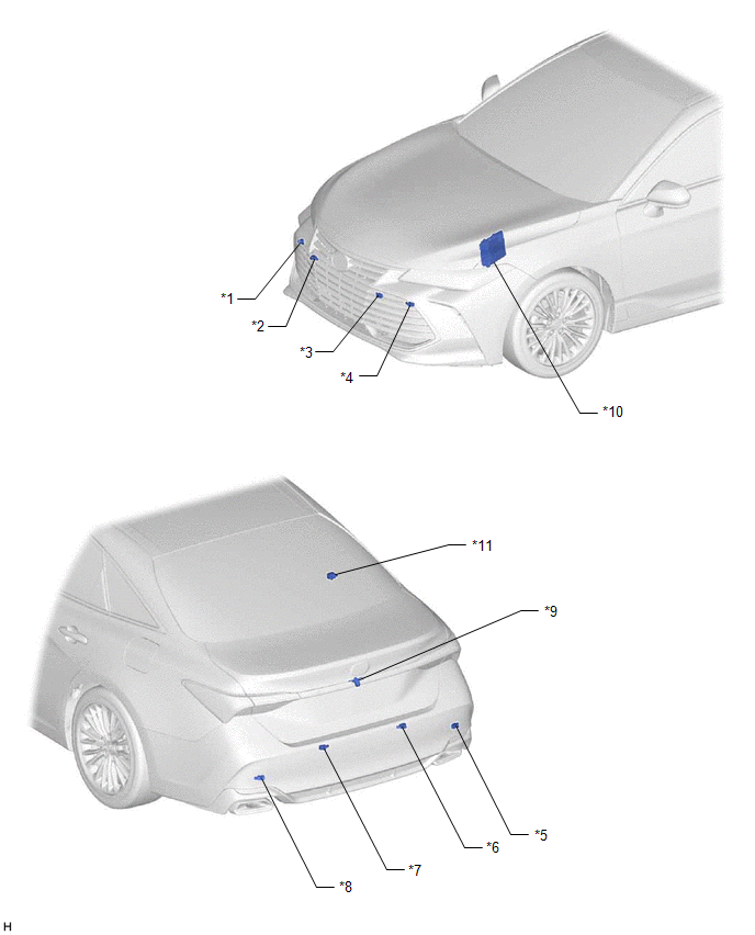
|
*1 | FRONT CORNER ULTRASONIC SENSOR RH |
*2 | FRONT CENTER ULTRASONIC SENSOR RH |
|
*3 | FRONT CENTER ULTRASONIC SENSOR LH |
*4 | FRONT CORNER ULTRASONIC SENSOR LH |
|
*5 | REAR CORNER ULTRASONIC SENSOR RH |
*6 | REAR CENTER ULTRASONIC SENSOR RH |
|
*7 | REAR CENTER ULTRASONIC SENSOR LH |
*8 | REAR CORNER ULTRASONIC SENSOR LH |
|
*9 | TELEVISION CAMERA ASSEMBLY (w/ Parking Assist Monitor System) |
*10 | ECM |
|
*11 | NO. 2 CLEARANCE WARNING BUZZER |
- | - |
ILLUSTRATION
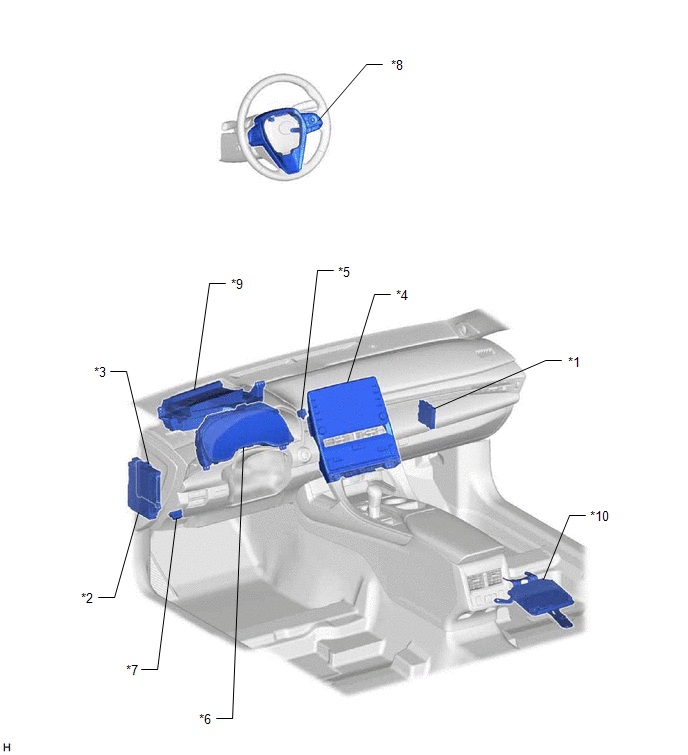
|
*1 | CLEARANCE WARNING ECU ASSEMBLY |
*2 | INSTRUMENT PANEL JUNCTION BLOCK ASSEMBLY
- ECU-IG1 NO. 4 FUSE |
|
*3 | MAIN BODY ECU (MULTIPLEX NETWORK BODY ECU) |
*4 | RADIO AND DISPLAY RECEIVER ASSEMBLY
- MULTI-DISPLAY |
|
*5 | NO. 1 CLEARANCE WARNING BUZZER |
*6 | COMBINATION METER ASSEMBLY
- MULTI-INFORMATION DISPLAY |
|
*7 | DLC3 |
*8 | STEERING PAD SWITCH ASSEMBLY |
|
*9 | HEADUP DISPLAY (METER MIRROR SUB-ASSEMBLY)(w/ Headup Display System) |
*10 | PARKING ASSIST ECU (w/ Panoramic View Monitor System) |
Precaution
PRECAUTION
PRECAUTION FOR DISCONNECTING CABLE FROM NEGATIVE BATTERY TERMINAL
NOTICE:
When
disconnecting the cable from the negative (-) battery terminal,
initialize the following systems after the cable is reconnected.
|
System Name | See Procedure |
|
Lane Departure Alert System (w/ Steering Control) |
 |
|
Intelligent Clearance Sonar System |
|
Parking Assist Monitor System |
|
Panoramic View Monitor System |
|
Pre-collision System |
|
Lighting System (for Gasoline Model with Cornering Light) |
PRECAUTIONS FOR INTUITIVE PARKING ASSIST SYSTEM
(a) Under the following conditions, the detection function may not function properly:
(1)
A sensor is covered with foreign matter, such as mud or snow (detection
function returns to normal when the sensor is cleaned).
(2) A sensor is frozen (detection function returns to normal when the temperature of the sensor rises).
(3) A hand is blocking a sensor.
HINT:
- In very cold weather where a malfunction display appears, the sensor may not be able to detect obstacles.
- If the malfunction display appears, visually check the sensor first. If
the sensor is free of foreign matter but the malfunction display
remains, the sensor may be malfunctioning.
(b) The detection range may be affected by the following conditions:
(1) A sensor is covered with foreign matter, such as mud or snow.
(2) The vehicle is in an excessively hot or excessively cold area.
(c) Under the following conditions, a detection error may occur:
(1) Driving on a bumpy road, an unpaved road or in tall grass.
(2)
Ultrasonic waves are received from the horn or parking sonar system of
another vehicle, a motorcycle engine, or the air brakes of a large
vehicle.
(3) It is raining heavily or the sensor is sprayed with water.
(4) The vehicle is tilted at a steep angle.
(5) The vehicle is equipped with a fender pole or a wireless antenna mechanism.
(6) A sensor is covered with foreign matter, such as mud or snow.
(7) The vehicle is moving forward or backward towards high curbs or objects that are perpendicular to the ground.
(8) A sensor is sprayed with high pressure water or steam.
(9) A towing hitch is mounted on the vehicle.
(d) The sensors cannot detect the following objects:
(1) Thin objects, such as wires and ropes
(2) Materials that absorb ultrasonic waves, such as cotton or snow.
(3) Objects with sharp edges
(4) Short objects
(5) Objects that are tall and protrude toward the vehicle above the detection range of the sensors.
(e) Other notices:
(1)
The sensors cannot detect objects directly under the bumper. (A sensor
may detect low objects and thin poles, and then lose track of them.)
(2)
Be aware that the detection range of this system is limited. In certain
conditions, some objects may not be detected. Always make sure to check
all around the vehicle when driving or parking.
(3) The sensors may not be able to detect obstacles that are too close to the sensors.
(4) The sensors may not be able to detect obstacles if the sensors have been dropped or subjected to a strong impact.
Problem Symptoms Table
PROBLEM SYMPTOMS TABLE
HINT:
- Use the table below to help determine the cause of problem symptoms. If
multiple suspected areas are listed, the potential causes of the
symptoms are listed in order of probability in the "Suspected Area"
column of the table. Check each symptom by checking the suspected areas
in the order they are listed. Replace parts as necessary.
- Inspect the fuses and relays related to this system before inspecting the suspected areas below.
- When an open circuit or frozen indication is displayed by the self-check
function, check for DTCs and troubleshoot according to each inspection
procedure.
General |
Symptom | Suspected Area |
Link |
|
System does not operate at all |
Proceed to "Clearance Warning ECU Power Source Circuit" |
 |
|
CAN communication system |
|
|
Clearance warning ECU assembly |
|
|
System cannot be turned off |
CAN communication system |
|
|
Clearance warning ECU assembly |
|
Sonar Function |
Symptom | Suspected Area |
Link |
| Combination
meter assembly (shift selection) operates normally, but detection
operates when shift lever is in P, or detection does not operate when
shift lever is in any position other than P (front sonar) |
CAN communication system |
|
|
Clearance warning ECU assembly |
|
|
Combination
meter assembly (shift selection) operates normally, but detection
operates when shift lever is not in R, or does not operate with shift
lever in R (rear sonar) | CAN communication system |
|
|
Clearance warning ECU assembly |
|
|
Combination
meter assembly (speedometer) operates normally, but detection does not
operate when vehicle speed meets operation condition, or detection
operates when vehicle speed does not meet operation condition (front
sonar) | CAN communication system |
|
|
Clearance warning ECU assembly |
|
Buzzer Function |
Symptom | Suspected Area |
Link |
|
Sonar detection operation is normal but buzzer operation is intermittent |
Check that the temporary mute function is not operating |
- |
| Proceed to "No. 1 Clearance Warning Buzzer Circuit" |
|
|
Proceed to "No. 2 Clearance Warning Buzzer Circuit" |
|
|
Clearance warning ECU assembly |
|
Display Function |
Symptom | Suspected Area |
Link |
|
Detection operation is normal but clearance sonar indicator does not illuminate |
CAN communication system |
|
|
Combination meter assembly |
|
|
Clearance warning ECU assembly |
|
|
Detection operation is normal but all sonar displays do not appear on multi-information display and multi-display |
CAN communication system |
|
|
Clearance warning ECU assembly |
|
|
Detection operation is normal but sonar displays do not appear on multi-information display |
CAN communication system |
|
|
Combination meter assembly |
|
|
Clearance warning ECU assembly |
|
|
Detection operation is normal but sonar displays do not appear on the full screen display (on the multi-display) |
CAN communication system |
|
|
Radio and display receiver assembly |
|
|
Clearance warning ECU assembly |
|
|
Detection operation is normal but sonar displays do not appear on the cooperated display (on the multi-display)*1 |
CAN communication system |
|
|
Radio and display receiver assembly |
|
|
Parking Assist ECU |
|
|
Clearance warning ECU assembly |
|
|
Detection operation is normal but sonar displays do not appear on the cooperated display (on the multi-display)*2 |
CAN communication system |
|
|
Radio and display receiver assembly |
|
|
Television Camera Assembly |
|
|
Clearance warning ECU assembly |
|
|
Detection operation is normal but sonar displays do not appear on the cooperated display (on the headup display)*3 |
CAN communication system |
|
|
Headup display (meter mirror sub-assembly) |
|
|
Clearance warning ECU assembly |
|
- *1: w/ Panoramic View Monitor System
- *2: w/ Parking Assist Monitor System
- *3: w/ Headup Display System
System Description
SYSTEM DESCRIPTION
GENERAL
(a)
This system uses ultrasonic sensors to detect any obstacles at the
corners and the rear of the vehicle. The system then informs the driver
of the distance between the sensors and an obstacle as well as their
positions by indicating them on the multi-information display (on the
combination meter assembly), multi-display (on the radio and display
receiver assembly) and by sounding a buzzer.
FUNCTION OF COMPONENTS
|
Component | Function |
|
Ultrasonic Sensor | Detects the distance between the vehicle and an obstacle |
- No. 1 Clearance Warning Buzzer
- No. 2 Clearance Warning Buzzer
| Sounds to inform the driver according to the distance to an obstacle |
|
Multi-information Display (on Combination Meter Assembly) |
- Displays the location of an obstacle and the approximate distance between the vehicle and the obstacle
- Displays a malfunction of the ultrasonic sensor to inform the driver
|
| Clearance Sonar Indicator (on Combination Meter Assembly) |
Illuminates
to inform the driver while the intuitive parking assist system power is
on (the engine switch is on (IG) and the intuitive parking assist
system is on) |
| Combination Meter Assembly |
Transmits the ON/OFF signal to the clearance warning ECU assembly |
|
Steering Pad Switch Assembly | Enables,
disables or cuts off the operation of the intuitive parking assist
system by transmitting the switch operation signal to the combination
meter assembly |
| Clearance Warning ECU Assembly |
- Judges the approximate distance between the vehicle and an obstacle
based on the signals from the ultrasonic sensors and sends it to the
multi-information display and radio and display receiver assembly
- Judges the approximate distance between the vehicle and an obstacle
based on the signals from the ultrasonic sensors and sounds the buzzer
- Receives the temporary mute setting signal and clearance sonar setting
screen information from the combination meter assembly via CAN
communication
|
| Main Body ECU (Multiplex Network Body ECU) |
Transmits the destination information to the clearance warning ECU assembly |
|
ECM | Transmits the shift position signal to the clearance warning ECU assembly |
|
Radio and Display Receiver Assembly - Multi-display |
- Receives the ultrasonic sensor information via CAN communication and
sends it to the multi-display through the digital communication line
- Transmits the customize information on the multi-display assembly to the clearance warning ECU assembly
- Sends the temporary mute setting signal and clearance sonar setting
screen information to the clearance warning ECU assembly via CAN
communication
|
- Parking Assist ECU*1
- Television Camera Assembly*2
| Receives
the ultrasonic sensor information via CAN communication and sends it to
the multi-display through the video signal cable. |
|
Headup Display (Meter Mirror Sub-assembly)*3 |
Receives the ultrasonic sensor information via CAN communication and sends it to the headup display |
- *1: w/ Panoramic View Monitor System
- *2: w/ Parking Assist Monitor System
- *3: w/ Headup Display System
OPERATION EXPLANATION
(a)
The operating conditions of each ultrasonic sensor differ according to
the installation position as shown in the table below.
|
Installation Position | Operating Condition |
|
Front Corner |
- Engine switch is on (IG).
- Intuitive parking assist system is on.
- Shift lever in any position other than P.
- Vehicle speed is less than approximately 10 km/h (6 mph).
|
| Front Center |
- Engine switch is on (IG).
- Intuitive parking assist system is on.
- Shift lever in any position other than P or R.
- Vehicle speed is less than approximately 10 km/h (6 mph).
|
| Rear Corner |
- Engine switch is on (IG).
- Intuitive parking assist system is on.
- Shift lever is in R.
- Vehicle speed is less than approximately 10 km/h (6 mph).
|
| Rear Center |
When
the system operates, the clearance warning ECU assembly transmits
ultrasonic waves from the ultrasonic sensors. If these waves encounter
an obstacle within one or more of the sensors ranges, the waves are
reflected back to the sensors, which transmit them to the clearance
warning ECU assembly.
Based on this information,
the clearance warning ECU assembly sends signals to the radio and
display receiver assembly, the combination meter assembly and the No. 1
clearance warning buzzer and the No. 2 clearance warning buzzer. The
approximate distance between the vehicle and the obstacle is then
indicated, and the buzzer sounds.
HINT:
Refer to Detection Range Measurement and Display Inspection.
Click here 
COMMUNICATION SIGNALS OF COMPONENTS
HINT:
- Allocation refers to the process of the clearance warning ECU assembly setting aside IDs for the sensors.
- The vehicle has the sensors arranged in 2 groups. There is a front
series and a rear series. The sensors are connected in a "daisy chain".
(a) Initialization mode:
An ID is allocated to each sensor and sensor diagnosis is performed.
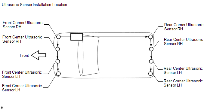
(1)
When the initial check is operating (the engine switch is on (IG) and
the intuitive parking assist system is on), the clearance warning ECU
assembly provides power to the first sensors in each series (front
corner ultrasonic sensor RH and rear corner ultrasonic sensor RH).
(2)
After the power is supplied, the front corner ultrasonic sensor RH and
rear corner ultrasonic sensor RH enter standby mode to receive an ID
from the ECU. When a certain amount of time has elapsed, the ECU sends
an ID allocation signal to these sensors.
(3) The
front corner ultrasonic sensor RH and rear corner ultrasonic sensor RH
receive the ID allocation signal from the ECU and perform
self-diagnosis. When the sensor self-diagnosis is complete, the ECU
sends an ID allocation confirmation signal to the sensors.
(4)
After the ID allocation confirmation is performed, the ECU provides
power to the second sensors in each series (front center ultrasonic
sensor RH and rear center ultrasonic sensor RH) via the first sensors.
In the same manner as the first sensors, the second sensors enter
standby mode. When a certain amount of time has elapsed, the ECU sends
an ID allocation signal to the second sensors.
(5)
The above operation will be repeated until an ID is allocated to the
last sensor (front corner ultrasonic sensor LH or rear corner ultrasonic
sensor LH). Initialization ends when ID allocation to all ultrasonic
sensors is completed.
(b) Detection mode:
After
initialization mode is completed, the system switches to detection
mode. In detection mode, the clearance warning ECU assembly sends
information request signals and sensor activation signals to the
ultrasonic sensors and receives detection result signals from the
sensors.
(1) The ECU regularly sends ID signals,
information request signals, and sensor activation signals to each
ultrasonic sensor according to the communication schedule.
(2)
When a certain amount of time has elapsed (sensor detection operation
is completed), the ECU sends an ID signal to the sensor to receive a
detection result signal.
(3) The ultrasonic sensor sends a detection result signal or detection information signal to the ECU.
(4) The above operation is performed repeatedly for each ultrasonic sensor.
System Diagram
SYSTEM DIAGRAM
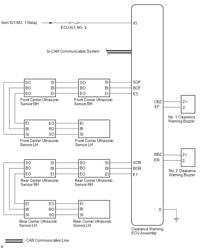
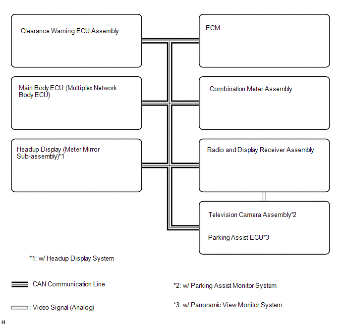 Communication Table
 |
Sender | Receiver |
Signal | Line |
|
Main Body ECU (Multiplex Network Body ECU) |
Clearance Warning ECU Assembly | Destination information signal |
CAN Communication Line |
| ECM |
Clearance Warning ECU Assembly | Shift position signal |
CAN Communication Line |
| Combination Meter Assembly |
Clearance Warning ECU Assembly | Vehicle speed signal |
CAN Communication Line |
| Clearance Warning ECU Assembly |
Combination Meter Assembly |
- Sonar information signal
- Clearance sonar indicator illumination request signal
| CAN Communication Line |
|
Clearance Warning ECU Assembly | Television Camera Assembly*2 |
Sonar information signal | CAN Communication Line |
|
Clearance Warning ECU Assembly | Parking Assist ECU*1 |
Sonar information signal | CAN Communication Line |
|
Parking Assist ECU*1 | Radio and Display Receiver Assembly |
Video signal | Analog |
|
Television Camera Assembly*2 |
Radio and Display Receiver Assembly |
Video signal | Analog |
|
Clearance Warning ECU Assembly |
Headup Display (Meter Mirror Sub-assembly)*3 |
Sonar information signal |
CAN Communication Line |
- *1: w/ Panoramic View Monitor System
- *2: w/ Parking Assist Monitor System
- *3: w/ Headup Display System
Terminals Of Ecu
TERMINALS OF ECU
CLEARANCE WARNING ECU ASSEMBLY

(a) Disconnect the K34 clearance warning ECU assembly connector.
(b) Measure the voltage and resistance on the wire harness side connector according to the value(s) in the table below.
|
Terminal No. (Symbol) | Wiring Color |
Terminal Description | Condition |
Specified Condition |
|
K34-1 (IG) - K34-30 (E) |
B - BR | IG power source signal |
Engine switch off | Below 1 V |
|
Engine switch on (IG) |
11 to 14 V |
|
K34-30 (E) - Body ground |
BR - Body ground | Ground |
Always | Below 1 Ω |
(c) Reconnect the K34 clearance warning ECU assembly connector.
(d) Measure the voltage and check for pulses according to the value(s) in the table below.
|
Terminal No. (Symbol) | Wiring Color |
Terminal Description | Condition |
Specified Condition |
|
K34-4 (BOF) - K34-30 (E) |
R - BR | Power source for front sensor circuit |
Engine switch off | Below 1 V |
- Engine switch on (IG)
- Intuitive parking assist system on
| 11 to 14 V |
|
K34-6 (E5) - K34-30 (E) |
W - BR | Ground for front clearance sonar |
Always | Below 1 Ω |
|
K34-8 (SOF) - K34-30 (E) |
L - BR | Front sensor communication signal (Front clearance sonar sensor) |
- Engine switch on (IG)
- Intuitive parking assist system on
- Shift lever in any position other than P or R
- Vehicle speed is less than approximately 10 km/h (6 mph)
| Pulse generation
(Refer to waveform 1) |
|
K34-14 (CBZ) - K34-13 (EF) |
LG - L | Clearance warning buzzer signal |
Buzzer sounding | Pulse generation
(Refer to waveform 2) |
|
K34-15 (BBZ) - K34-16 (ER) |
G - P | Clearance warning buzzer signal |
Buzzer sounding | Pulse generation
(Refer to waveform 2) |
|
K34-22 (BOR) - K34-30 (E) |
BE - BR | Power source for rear sensor circuit |
Engine switch off | Below 1 V |
- Engine switch on (IG)
- Intuitive parking assist system on
| 11 to 14 V |
|
K34-23 (E1) - K34-30 (E) |
GR - BR | Ground for rear clearance sonar |
Always | Below 1 Ω |
|
K34-24 (SOR) - K34-30 (E) |
SB - BR | Rear sensor communication signal (Rear clearance sonar sensor) |
- Engine switch on (IG)
- Intuitive parking assist system on
- Shift lever in R
- Vehicle speed is less than approximately 10 km/h (6 mph)
| Pulse generation
(Refer to waveform 1) |
(e) Using an oscilloscope, check waveform 1.
(1) Waveform 1 (Reference)

|
Item | Content |
|
Measurement terminal |
- CH1: K34-8 (SOF) - K34-30 (E)
- CH2: K34-24 (SOR) - K34-30 (E)
|
| Measurement setting |
5 V/DIV., 1 ms./DIV. |
|
Condition |
- Engine switch on (IG)
- Intuitive parking assist system on
- Shift lever in any position other than P or R (CH1)
- Shift lever in R (CH2)
- Vehicle speed is less than approximately 10 km/h (6 mph)
|
HINT:
The waveforms for CH1 and CH2 are same.
(f) Using an oscilloscope, check waveform 2.
(1) Waveform 2 (Reference)
|
Item | Content |
|
Measurement terminal |
- K34-14 (CBZ) - K34-13 (EF)
- K34-15 (BBZ) - K34-16 (ER)
|
| Measurement setting |
2 V/DIV., 500 ÎĽs./DIV. |
|
Condition | Buzzer sounding |
HINT:
The amplitude of the waveform changes according to the set volume.
Control Module Communication Bus "A" Off (U0073,U0155)
DESCRIPTION
These DTCs are
stored when the clearance warning ECU assembly cannot receive and
recognize several signals via the CAN communication line.
|
DTC No. | Detection Item |
DTC Detection Condition | Trouble Area |
|
U0073 | Control Module Communication Bus "A" Off |
Control module communication bus off |
CAN communication system |
|
U0155 | Lost Communication with Instrument Panel Cluster (IPC) Control Module |
Lost communication with the combination meter assembly |
CAN communication system |
HINT:
When 2 or more DTCs starting with "U" are output simultaneously, inspect the connectors and wire harnesses of each ECU.
PROCEDURE
(a) Clear the DTCs
Body Electrical > Advanced Parking Guidance/ICS/Intuitive P/A > Clear DTCs
(b) Check for CAN communication system DTCs
Body Electrical > Advanced Parking Guidance/ICS/Intuitive P/A > Trouble Codes
|
Result | Proceed to |
|
CAN communication system DTCs are output |
A |
| No CAN communication system DTCs are output |
B |
| A |
 | GO TO CAN COMMUNICATION SYSTEM |
| B |
| USE SIMULATION METHOD TO CHECK |
CAN Communication Failure (Message Registry) (U1000)
DESCRIPTION
If DTC U1000 is
stored frequently, duplicate the conditions that cause the problem
symptoms and perform troubleshooting again even if the DTC is not output
when rechecking for DTCs.
|
DTC No. | Detection Item |
DTC Detection Condition | Trouble Area |
|
U1000 | CAN Communication Failure (Message Registry) |
ECU malfunction | Clearance warning ECU assembly |
PROCEDURE
(a) Clear the DTCs.
Body Electrical > Advanced Parking Guidance/ICS/Intuitive P/A > Clear DTCs
(b) Check for DTCs.
Body Electrical > Advanced Parking Guidance/ICS/Intuitive P/A > Trouble Codes
OK:
DTC U1000 is not output.
HINT:
If
these DTCs are output frequently, duplicate the conditions that cause
the problem symptoms and perform troubleshooting again, even if the DTC
was not output when rechecking for DTCs.
Click here

| OK |  |
USE SIMULATION METHOD TO CHECK |
| NG |
| REPLACE CLEARANCE WARNING ECU ASSEMBLY |


