Confirm Cellular Phone Functionality
PROCEDURE
|
1. | CHECK CUSTOMER'S CELLULAR PHONE COMPATIBILITY |
(a) Check if the cellular phone is compatible (Refer to http://www.toyota.com/Entune/).
|
Result | Proceed to |
|
Cellular phone is compatible. |
A |
| Cellular phone is not compatible. |
B |
HINT:
It is important to check the cellular phone compatibility charts carefully:
- Some apps may only work on cellular phones.
- Some apps may only work when paired to a vehicle.
- Some cellular phones do not support all features.
| B |
 | RECOMMEND COMPATIBLE CELLULAR PHONE |
|
A |
 | |
| 2. |
CONFIRM CELLULAR PHONE SIGNAL |
(a)
A 3G or higher connection is required for proper Toyota Entune App
Suite Connect functionality. If a 3G or higher connection is not
available, some apps may not function properly.
|
NEXT | |
| |
| 3. |
CONFIRM THE TOYOTA ENTUNE APP SUITE CONNECT APP IS DOWNLOADED TO THE CUSTOMER'S CELLULAR PHONE |
(a) Turn the cellular phone on.
(b) Check that the Toyota Entune App Suite Connect app has been downloaded.
|
Result | Proceed to |
|
Toyota Entune App Suite Connect app has not been downloaded. |
A |
| Toyota Entune App Suite Connect app has been downloaded. |
B |
| B |
| GO TO STEP 5 |
|
A | |
| |
| 4. |
DOWNLOAD TOYOTA ENTUNE APP SUITE CONNECT APP |
(a) Download the Toyota Entune App Suite Connect app.
|
Result | Proceed to |
|
Toyota Entune App Suite Connect app downloaded successfully. |
A |
| Toyota Entune App Suite Connect app did not download successfully. |
B |
HINT:
Contact
the service provider or cellular phone manufacturer if assistance is
required for downloading the Toyota Entune App Suite Connect app or
resetting the customer's cellular phone.
| B |
| RESET CUSTOMER'S CELLULAR PHONE (REMOVE BATTERY) AND TRY AGAIN |
|
A | |
| |
| 5. |
CHECK IF THE CUSTOMER'S ACCOUNT IS VALID AND ACTIVE |
(a) Start the Toyota Entune App Suite Connect app on the customer's cellular phone.
(b) Sign out of the account (if currently signed in).
(c) Sign in using the customer's account information.
|
Result | Proceed to |
|
Sign in to Toyota Entune App Suite Connect app is not successful. |
A |
| Sign in to Toyota Entune App Suite Connect app is successful. |
B |
HINT:
The purpose of signing out of the account and then signing back in is to ensure that the correct account is used.
| B |
| GO TO STEP 9 |
|
A | |
| |
| 6. |
RECORD ERROR MESSAGES IF PRESENT |
|
NEXT | |
| |
| 7. |
CONFIRM THE CUSTOMER'S CELLULAR PHONE WITH A KNOWN GOOD ENTUNE ACCOUNT (e.g. DEALER DEMO ACCOUNT) |
(a) Start the Toyota Entune App Suite Connect app on the customer's cellular phone.
(b) Sign out of the customer's account (if currently signed in).
(c) Sign in using a known good Toyota Entune account (e.g. dealer demo account).
|
Result | Proceed to |
|
Sign in using known good account is successful. |
A |
| Sign in using known good account is not successful. |
B |
HINT:
- The purpose of signing out of the account and then signing back in is to ensure that the correct account is used.
- Upon completion of this procedure, be sure to sign out of the known good account on the customer's cellular phone.
- If sign in using a known good account is successful, the customer's
account has a problem. Instruct the customer to visit
http://www.toyota.com/Entune/ or contact Entune customer support for
account status verification.
| A |
| CUSTOMER ACCOUNT ISSUE (SIGN OUT OF THE DEALER DEMO ACCOUNT) |
|
B | |
| |
| 8. |
CONFIRM TOYOTA ENTUNE SERVICES ARE AVAILABLE |
(a) Start the Toyota Entune App Suite Connect app on a known good cellular phone.
(b) Sign out of the account (if currently signed in).
(c) Sign in using a known good Toyota Entune account (e.g. dealer demo account).
|
Result | Proceed to |
|
Sign in to Toyota Entune App Suite Connect app is successful. |
A |
| Sign in to Toyota Entune App Suite Connect app is not successful. |
B |
HINT:
Contact
the service provider or cellular phone manufacturer if assistance is
required for resetting the customer's cellular phone.
| A |
| RESET CUSTOMER'S CELLULAR PHONE (REMOVE BATTERY) AND TRY AGAIN |
| B |
| TOYOTA ENTUNE SERVICES ARE CURRENTLY UNAVAILABLE |
| 9. |
CHECK TOYOTA ENTUNE SEARCH FUNCTION ON CUSTOMER'S CELLULAR PHONE |
(a) Sign in to the Toyota Entune App Suite Connect app on the customer's cellular phone.
(b) Start a search app (e.g. Bing) within the Toyota Entune App Suite Connect app.
(c) Check that a search can be made.
|
Result | Proceed to |
|
App search is successful. |
A |
| App search is not successful. |
B |
| A |
| PROCEED TO NEXT SUSPECTED AREA SHOWN IN PROBLEM SYMPTOMS TABLE |
|
B | |
| |
| 10. |
RECORD ERROR MESSAGES IF PRESENT |
|
NEXT | |
| |
| 11. |
CHECK TOYOTA ENTUNE SEARCH FUNCTION ON KNOWN GOOD CELLULAR PHONE |
(a) Sign in to the Toyota Entune App Suite Connect app on a known good cellular phone.
(b) Start a search app (e.g. Bing) within the Toyota Entune App Suite Connect app.
(c) Check that a search can be made.
|
Result | Proceed to |
|
App search is successful. |
A |
| App search is not successful. |
B |
HINT:
Contact
the service provider or cellular phone manufacturer if assistance is
required for resetting the customer's cellular phone or known good
cellular phone.
| A |
| RESET CUSTOMER'S CELLULAR PHONE (REMOVE BATTERY) AND TRY AGAIN |
| B |
| RESET KNOWN GOOD CELLULAR PHONE (REMOVE BATTERY) AND TRY AGAIN |
Confirm Vehicle Headunit Functionality
PROCEDURE
|
1. | CHECK CUSTOMER'S CELLULAR PHONE COMPATIBILITY |
(a) Check if the cellular phone is compatible (Refer to http://www.toyota.com/Entune/).
|
Result | Proceed to |
|
Cellular phone is compatible. |
A |
| Cellular phone is not compatible. |
B |
HINT:
It is important to check the cellular phone compatibility charts carefully:
- Some apps may only work on cellular phones.
- Some apps may only work when paired to a vehicle.
- Some cellular phones do not support all features.
| B |
 | RECOMMEND COMPATIBLE CELLULAR PHONE |
|
A |
 | |
| 2. |
CONFIRM CELLULAR PHONE SIGNAL |
(a)
A 3G or higher connection is required for proper Toyota Entune App
Suite Connect functionality. If a 3G or higher connection is not
available, some applications may not function properly.
|
NEXT | |
| |
| 3. |
CONFIRM IF THE CUSTOMER'S CELLULAR PHONE CAN BE PAIRED TO THE VEHICLE |
(a) Pair the customer's cellular phone to the vehicle.
|
Result | Proceed to |
|
Cellular phone is not successfully paired. |
A |
| Cellular phone is successfully paired. |
B |
| B |
| GO TO STEP 5 |
|
A | |
| |
| 4. |
CONFIRM THAT A KNOWN GOOD CELLULAR PHONE CAN BE PAIRED TO THE VEHICLE |
(a) Check that a known good cellular phone can be paired to the customer's vehicle.
|
Result | Proceed to |
|
Cellular phone is successfully paired. |
A |
| Cellular phone is not successfully paired. |
B |
HINT:
For instructions on how to reset the cellular phone, refer to the appropriate manufacturer's website.
| A |
| RESET CUSTOMER'S CELLULAR PHONE (REMOVE BATTERY) AND TRY AGAIN |
| B |
| GO TO STEP 12 |
| 5. |
CHECK APPS FUNCTION WHEN PAIRED |
(a) Proceed to the appropriate step based on the customer concern in the table below.
|
Result | Proceed to |
|
Head unit data apps (e.g. internet search) do not function properly. |
A |
| Head unit internet radio apps do not function properly. |
B |
HINT:
This is a head unit functionality check. Ensure that a cellular phone is paired to the vehicle.
| B |
| GO TO STEP 9 |
|
A | |
| |
| 6. |
CHECK DATA APPS FUNCTION ON THE HEAD UNIT |
(a) Make sure that the customer's cellular phone is paired with the vehicle.
(b) Start an internet search app on the head unit.
(c) Check if a search can be made.
|
Result | Proceed to |
|
Head unit data apps do not function properly. |
A |
| Head unit data apps function properly. |
B |
| B |
| END (NO PROBLEM WAS FOUND) |
|
A | |
| |
| 7. |
RECORD ERROR MESSAGES IF PRESENT |
|
NEXT | |
| |
| 8. |
CHECK TOYOTA ENTUNE SEARCH FUNCTION ON THE HEAD UNIT USING A KNOWN GOOD CELLULAR PHONE |
(a) Make sure that a known good cellular phone is paired with the vehicle.
(b) Start an internet search app on the head unit.
(c) Check if a search can be made.
|
Result | Proceed to |
|
Head unit data apps function properly. |
A |
| Head unit data apps do not function properly. |
B |
HINT:
For instructions on how to reset the cellular phone, refer to the appropriate manufacturer's website.
| A |
| RESET CUSTOMER'S CELLULAR PHONE (REMOVE BATTERY) AND TRY AGAIN |
| B |
| GO TO STEP 12 |
| 9. |
CHECK INTERNET RADIO FUNCTION ON THE HEAD UNIT USING THE CUSTOMER'S CELLULAR PHONE |
(a) Make sure that the customer's cellular phone is paired with the vehicle.
(b) Start an internet radio app on the head unit.
(c) Check that the audio can be heard through the vehicle's speakers.
|
Result | Proceed to |
|
Head unit internet radio apps do not function properly. |
A |
| Head unit internet radio apps function properly. |
B |
| B |
| END (NO PROBLEM WAS FOUND) |
|
A | |
| |
| 10. |
RECORD ERROR MESSAGES IF PRESENT |
|
NEXT | |
| |
| 11. |
CHECK INTERNET RADIO FUNCTION ON THE HEAD UNIT USING A KNOWN GOOD CELLULAR PHONE |
(a) Make sure that a known good cellular phone is paired with the vehicle.
(b) Start an internet radio app on the head unit.
(c) Check that the audio can be heard through the speakers.
|
Result | Proceed to |
|
Head unit internet radio apps do not function properly using a known good cellular phone. |
A |
| Head unit internet radio apps function properly using known good cellular phone. |
B |
HINT:
For instructions on how to reset the cellular phone, refer to the appropriate manufacturer's website.
| B |
| RESET CUSTOMER'S CELLULAR PHONE (REMOVE BATTERY) AND TRY AGAIN |
|
A | |
| |
| 12. |
PERFORM TOYOTA ENTUNE APP SUITE CONNECT RESET PROCEDURE |
(a) Perform the Toyota Entune App Suite Connect reset procedure.
Click here

|
Result | Proceed to |
|
The problem symptom has been repaired. |
A |
| The problem symptom has not been repaired. |
B |
| A |
| END |
| B |
| PROCEED TO NEXT SUSPECTED AREA SHOWN IN PROBLEM SYMPTOMS TABLE |
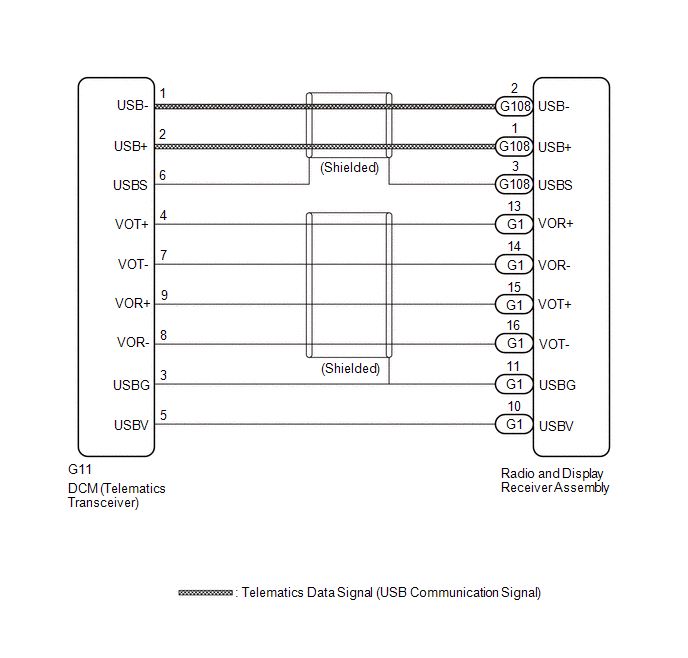
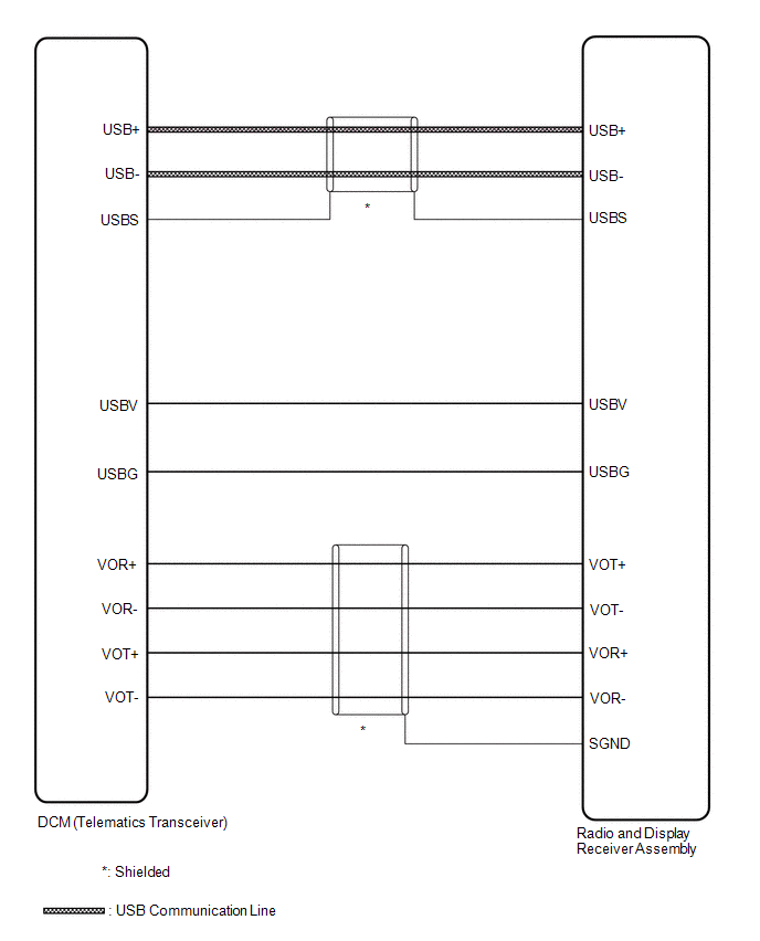
DCM Data Signal Circuit between Navigation ECU and DCM
DESCRIPTION
This circuit is
used to send and receive signals between the DCM (Telematics
Transceiver) and radio and display receiver assembly.
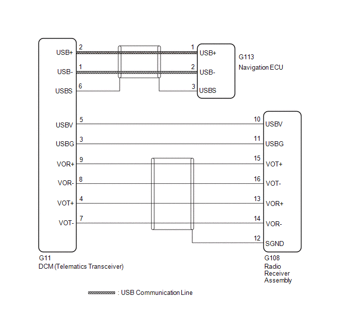
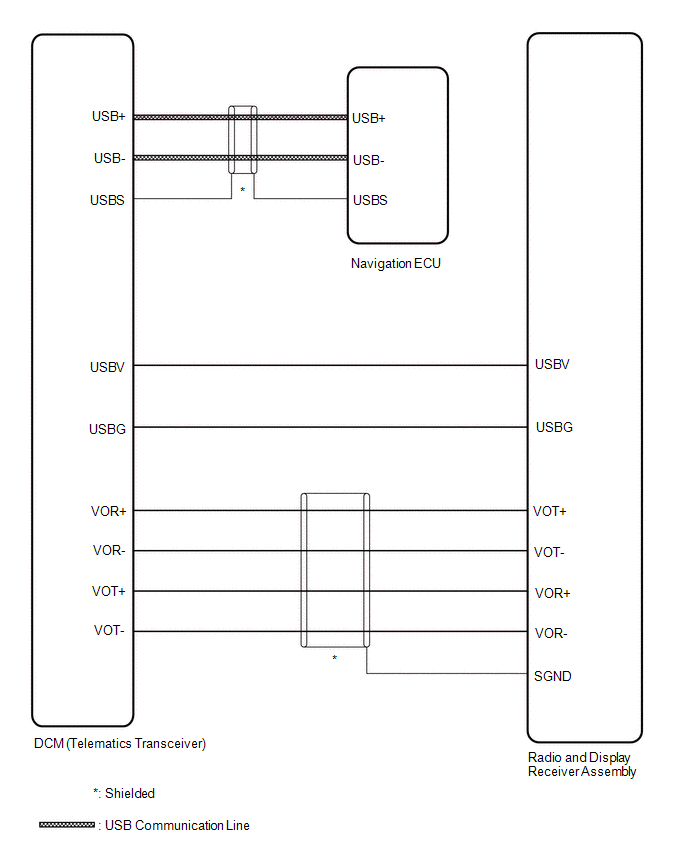
WIRING DIAGRAM
w/o Navigation System
 w/ Navigation System
PROCEDURE
(a) Choose the model to be inspected.
| Result |
Proceed to |
| w/o Navigation System |
A |
| w/ Navigation System |
B |
| B |
 | GO TO STEP 3 |
|
A |
 | |
| 2. |
CHECK HARNESS AND CONNECTOR (RADIO AND DISPLAY RECEIVER ASSEMBLY - DCM (TELEMATICS TRANSCEIVER)) |
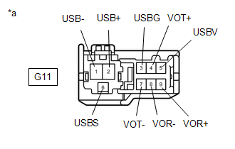
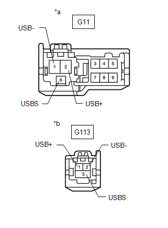
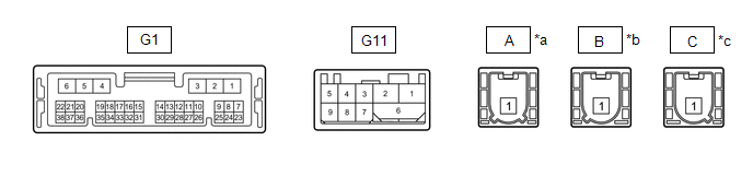
| (a) Disconnect the G11 DCM (Telematics Transceiver) connector. |
 |
|
*a | Front view of wire harness connector
(to DCM (Telematics Transceiver)) | | |
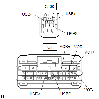
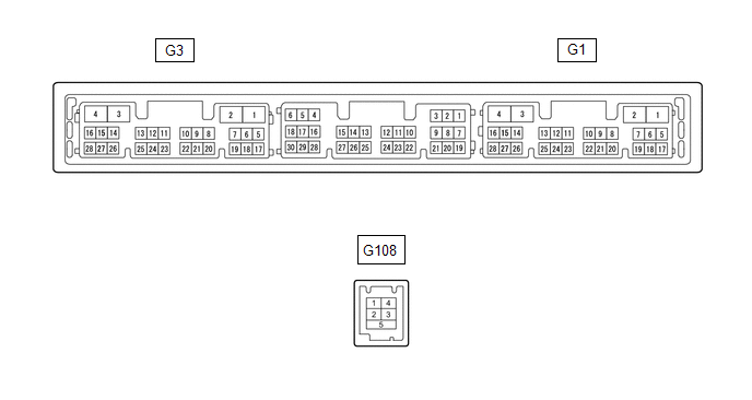
| (b) Disconnect the G1 and G108 radio and display receiver assembly connector. |
 |
|
*a | Front view of wire harness connector
(to Radio and Display Receiver Assembly) | | |
(c) Measure the resistance according to the value(s) in the table below.
Standard Resistance:
|
Tester Connection | Condition |
Specified Condition |
|
G11-1 (USB-) - G108-2 (USB-) |
Always | Below 1 Ω |
|
G11-2 (USB+) - G108-1 (USB+) |
Always | Below 1 Ω |
|
G11-6 (USBS) - G108-3 (USBS) |
Always | Below 1 Ω |
|
G11-3 (USBG) - G1-11 (USBG) |
Always | Below 1 Ω |
|
G11-4 (VOT+) - G1-13 (VOR+) |
Always | Below 1 Ω |
|
G11-5 (USBV) - G1-10 (USBV) |
Always | Below 1 Ω |
|
G11-7 (VOT-) - G1-14 (VOR-) |
Always | Below 1 Ω |
|
G11-8 (VOR-) - G1-16 (VOT-) |
Always | Below 1 Ω |
|
G11-9 (VOR+) - G1-15 (VOT+) |
Always | Below 1 Ω |
|
G11-1 (USB-) or G108-2 (USB-) - Body ground |
Always | 10 kΩ or higher |
|
G11-2 (USB+) or G108-1 (USB+) - Body ground |
Always | 10 kΩ or higher |
|
G11-6 (USBS) or G108-3 (USBS) - Body ground |
Always | 10 kΩ or higher |
|
G11-3 (USBG) or G1-11 (USBG) - Body ground |
Always | 10 kΩ or higher |
|
G11-4 (VOT+) or G1-13 (VOR+) - Body ground |
Always | 10 kΩ or higher |
|
G11-5 (USBV) or G1-10 (USBV) - Body ground |
Always | 10 kΩ or higher |
|
G11-7 (VOT-) or G1-14 (VOR-) - Body ground |
Always | 10 kΩ or higher |
|
G11-8 (VOR-) or G1-16 (VOT-) - Body ground |
Always | 10 kΩ or higher |
|
G11-9 (VOR+) or G1-15 (VOT+) - Body ground |
Always | 10 kΩ or higher |
| OK |
| PROCEED TO NEXT SUSPECTED AREA SHOWN IN PROBLEM SYMPTOMS TABLE |
| NG |
| REPAIR OR REPLACE HARNESS OR CONNECTOR |
| 3. |
CHECK HARNESS AND CONNECTOR (RADIO AND DISPLAY RECEIVER ASSEMBLY - DCM (TELEMATICS TRANSCEIVER)) |
(a) Disconnect the G11 DCM (Telematics Transceiver) connector.
(b) Disconnect the G108 radio and display receiver assembly connector.
(c) Measure the resistance according to the value(s) in the table below.
Standard Resistance:
|
Tester Connection | Condition |
Specified Condition |
|
G11-3 (USBG) - G108-11 (USBG) |
Always | Below 1 Ω |
|
G11-4 (VOT+) - G108-13 (VOR+) |
Always | Below 1 Ω |
|
G11-5 (USBV) - G108-10 (USBV) |
Always | Below 1 Ω |
|
G11-7 (VOT-) - G108-14 (VOR-) |
Always | Below 1 Ω |
|
G11-8 (VOR-) - G108-16 (VOT-) |
Always | Below 1 Ω |
|
G11-9 (VOR+) - G108-26 (VOT+) |
Always | Below 1 Ω |
|
G11-3 (USBG) or G108-11 (USBG) - Body ground |
Always | 10 kΩ or higher |
|
G11-4 (VOT+) or G108-13 (VOR+) - Body ground |
Always | 10 kΩ or higher |
|
G11-5 (USBV) or G108-10 (USBV) - Body ground |
Always | 10 kΩ or higher |
|
G11-7 (VOT-) or G108-14 (VOR-) - Body ground |
Always | 10 kΩ or higher |
|
G11-8 (VOR-) or G108-16 (VOT-) - Body ground |
Always | 10 kΩ or higher |
|
G11-9 (VOR+) or G108-26 (VOT+) - Body ground |
Always | 10 kΩ or higher |
| NG |
| REPAIR OR REPLACE HARNESS OR CONNECTOR |
|
OK | |
| |
| 4. |
CHECK HARNESS AND CONNECTOR (NAVIGATION ECU - DCM (TELEMATICS TRANSCEIVER)) |
| (a) Disconnect the G11 DCM (Telematics Transceiver) connector. |
 |
|
*a | Front view of wire harness connector
(to DCM (Telematics Transceiver)) | |
*b | Front view of wire harness connector
(to Navigation ECU) | | |
(b) Disconnect the G113 navigation ECU connector.
(c) Measure the resistance according to the value(s) in the table below.
Standard Resistance:
|
Tester Connection | Condition |
Specified Condition |
|
G11-1 (USB-) - G113-2 (USB-) |
Always | Below 1 Ω |
|
G11-2 (USB+) - G113-1 (USB+) |
Always | Below 1 Ω |
|
G11-6 (USBS) - G113-3 (USBS) |
Always | Below 1 Ω |
|
G11-1 (USB-) or G113-2 (USB-) - Body ground |
Always | 10 kΩ or higher |
|
G11-2 (USB+) or G113-1 (USB+) - Body ground |
Always | 10 kΩ or higher |
|
G11-6 (USBS) or G113-3 (USBS) - Body ground |
Always | 10 kΩ or higher |
| OK |
| PROCEED TO NEXT SUSPECTED AREA SHOWN IN PROBLEM SYMPTOMS TABLE |
| NG |
| REPAIR OR REPLACE HARNESS OR CONNECTOR |
Does not Recognize Voice Commands Performed to Contact Support Center
PROCEDURE
|
1. | CHECK COMMUNICATION BASED VOICE RECOGNITION FUNCTION |
(a)
While paying attention to the condition of the spoken voice command,
say "Find a gas station in New York" and check that voice recognition is
operating normally.
HINT:
- When the voice command is recognized, the content of the voice command
is displayed in the voice recognition result display area to the right
of the mic icon. (Example: When "Find a gas station in New York" is
spoken, "Find a gas station in New York" is displayed in the voice
recognition result display area.)
- If an unnecessary word (such as "um" or "ah") is spoken before or after
the recognition word, the system incorrectly recognizes the recognition
word.
- The system cannot recognize voice commands when multiple people are speaking simultaneously.
- If the speaking speed is too fast or too slow, the recognition rate may decrease.
- The system may have difficulty recognizing voice commands depending on
the voice quality (such as a hoarse voice due to poor physical
condition).
OK:
Voice command is recognized normally.
| OK |
 | END |
| NG |
| CONTACT SERVICE CENTER |
GPS Mark is not Displayed
CAUTION / NOTICE / HINT
NOTICE:
- Depending on the parts that are replaced during vehicle inspection or
maintenance, performing initialization, registration or calibration may
be needed. Refer to Precaution for Audio and Visual System.
Click here 
- The following may occur if a radio and display receiver assembly from
another vehicle is installed to this vehicle. Therefore, when replacing
the radio and display receiver assembly, be sure to replace it with a
new one.
- A communication malfunction DTC may be stored.
- The radio and display receiver assembly may not operate normally.
PROCEDURE
(a)
Check the cabin for any objects that might interrupt radio reception
and devices which use radio waves on the instrument panel. If such an
object exists, remove it and check if the GPS mark reappears.
HINT:
The
GPS uses extremely faint radio waves originating from satellites. If
the signal is interrupted by obstructions or other radio waves, the GPS
may not be able to properly receive the signal.
OK:
The GPS mark appears.
| OK |
 | END |
|
NG |
 | |
(a)
Check if the vehicle is in a location where GPS signal reception is
poor. If the vehicle is in such a place, relocate the vehicle and check
if the GPS mark reappears.
HINT:
The
GPS uses 24 satellites in 6 orbits. At any point in time, 4 satellites
should be able to pinpoint your vehicle. However, GPS signals may not
reach the vehicle due to influence from the surroundings, vehicle
direction and time. For examples, see the following illustration.
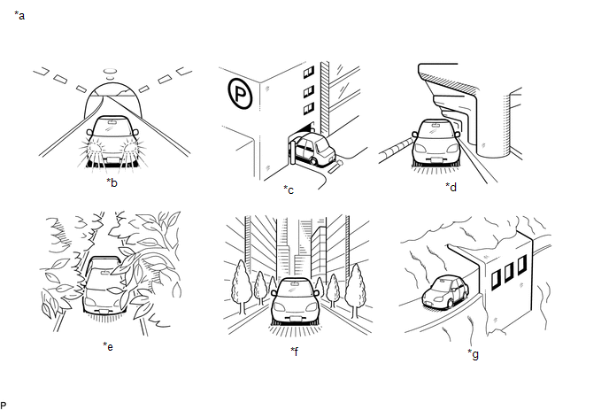
|
*a | Example |
*b | In a tunnel |
|
*c | In a building |
*d | Under an overpass |
|
*e | In a forest or on tree-lined path |
*f | Between tall buildings |
|
*g | Under a cliff or overhang |
- | - |
OK:
The GPS mark is displayed.
| OK |
| END (SYSTEM RETURNED TO NORMAL) |
|
NG | |
| |
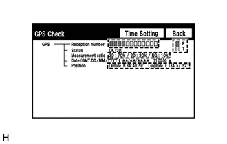
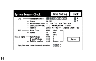
| 3. |
CHECK GPS INFORMATION (OPERATION CHECK) |
(a) Enter the "System Sensors Check" screen. Refer to Check GPS & Vehicle Sensors in Operation Check.
w/o Navigation System
 w/ Navigation System
w/o Navigation System: Click here
w/ Navigation System: Click here
(b) Check how many of the following codes appear in the "Reception number".
HINT:
T or P appears.
OK:
At least 3 codes appear.
| OK |
| REPLACE RADIO AND DISPLAY RECEIVER ASSEMBLY |
| NG |
| PROCEED TO NEXT SUSPECTED AREA SHOWN IN PROBLEM SYMPTOMS TABLE |
How To Proceed With Troubleshooting
CAUTION / NOTICE / HINT
HINT:
- Use the following procedure to troubleshoot the Entune system.
- *: Use the Techstream.
PROCEDURE
|
1. | VEHICLE BROUGHT TO WORKSHOP |
|
NEXT |
 | |
| 2. |
CHECK THE CUSTOMER'S CONTRACT STATUS |
(a)
Check if the satellite radio and Toyota Entune contracts are valid, or
if the contract period has ended using the vehicle inquiry function on
TIS.
|
Result | Proceed to |
|
Both Contracts are valid. |
A |
| Contract for satellite radio is not valid. |
B |
| Contract for Toyota Entune is not valid. |
C |
| B |
 | GO TO AUDIO AND VISUAL SYSTEM |
| C |
| GO TO SAFETY CONNECT SYSTEM |
|
A | |
| |
| 3. |
CHECK CAN COMMUNICATION SYSTEM* |
(a) Check if CAN communication system DTCs are output.
Click here 
|
Result | Proceed to |
|
CAN DTCs are not output. |
A |
| CAN DTCs are output. |
B |
| B |
| GO TO CAN COMMUNICATION SYSTEM |
|
A | |
| |
(a) Perform Health Check.
Click here
(b) Check for DTCs and note any codes that are output.
(c) Clear the DTCs.
(d) Recheck for DTCs. Try to reproduce the DTCs by simulating the conditions indicated by the DTCs.
|
Result | Proceed to |
|
DTCs are not output. |
A |
| Audio and visual system DTCs are output. |
B |
| Safety connect system DTCs are output. |
C |
| Entune system DTCs are output. |
D |
| Telematics system DTCs are output. |
E |
| B |
| GO TO AUDIO AND VISUAL SYSTEM |
| C |
| GO TO SAFETY CONNECT SYSTEM |
| D |
| GO TO DIAGNOSTIC TROUBLE CODE CHART |
| E |
| GO TO TELEMATICS SYSTEM |
|
A | |
| |
| 5. |
PROBLEM SYMPTOMS TABLE |
(a) Refer to Problem Symptoms Table.
Click here
|
Result | Proceed to |
|
Fault is not listed in Problem Symptoms Table. |
A |
| Fault is listed in Problem Symptoms Table. |
B |
HINT:
If the symptom does not recur and no DTCs are output, perform the simulation method.
Click here
| B |
| GO TO STEP 7 |
|
A | |
| |
| 6. |
PERFORM TROUBLESHOOTING* |
(a) Refer to Terminals of ECU.
Click here
|
NEXT | |
| |
|
NEXT | |
| |
| NEXT |
| END |
Operation Check
OPERATION CHECK
TOYOTA ENTUNE APP SUITE CONNECT RESET PROCEDURE
(a) Duplicate the problem symptom.
(b) Check for DTCs and repair the systems for which any DTCs are output.
Click here 
(c) Check cellular phone compatibility.
(1) Check if the cellular phone/vehicle is compatible (Refer to http://www.toyota.com/Entune/).
(2) If the cellular phone is not compatible, recommend to the customer a compatible cellular phone.
(d) Delete all paired devices from the cellular phone.
(1)
The procedure varies based on phone model. Contact the service provider
or cellular phone manufacturer if assistance is required.
(e) Remove the Toyota Entune App Suite Connect app from the phone.
NOTICE:
Only perform this step if the customer is present and approves.
(1)
The procedure varies based on phone model. Contact the service provider
or cellular phone manufacturer if assistance is required.
(f) Reset the phone.
NOTICE:
Only perform this step if the customer is present and approves.
(1)
Turn off the phone and remove the battery for 15 seconds. For
instructions on how to reset a cellular devices, refer to the
appropriate manufacturer's website.
(g) Reinstall the Toyota Entune App Suite Connect app on the phone. (If removed.)
(1)
The procedure varies based on phone model. Contact the service provider
or cellular phone manufacturer if assistance is required.
(h) Delete all personal data from the radio and display receiver assembly.
(1) Delete all personal data from the radio and display receiver assembly.
NOTICE:
Only perform this step if the customer is present and approves.
HINT:
Re-installation of applications must be completed before applications will appear on the radio and display receiver assembly.
(i) Disconnect the cable from the negative (-) auxiliary battery terminal.
NOTICE:
After
turning the power switch off, waiting time may be required before
disconnecting the cable from the negative (-) auxiliary battery
terminal. Therefore, make sure to read the disconnecting the cable from
the negative (-) auxiliary battery terminal notices before proceeding
with work.
Click here
(1) Record all radio station presets.
(2) Disconnect the cable from the negative (-) auxiliary battery terminal and leave it disconnected for 2 minutes.
(j) Check if the problem symptom disappears.
Parts Location
PARTS LOCATION
ILLUSTRATION
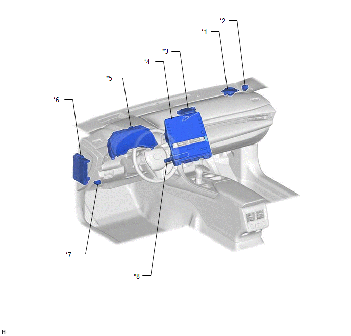
|
*1 | FRONT NO. 2 SPEAKER ASSEMBLY RH (for 8 Speakers) |
*2 | FRONT NO. 3 SPEAKER ASSEMBLY RH (for 14 Speakers) |
|
*3 | NAVIGATION ANTENNA ASSEMBLY
- Telephone Sub | *4 |
RADIO AND DISPLAY RECEIVER ASSEMBLY |
|
*5 | COMBINATION METER ASSEMBLY |
*6 | MAIN BODY ECU (MULTIPLEX NETWORK BODY ECU) |
|
*7 | DLC3 |
*8 | DCM (TELEMATICS TRANSCEIVER) |
ILLUSTRATION
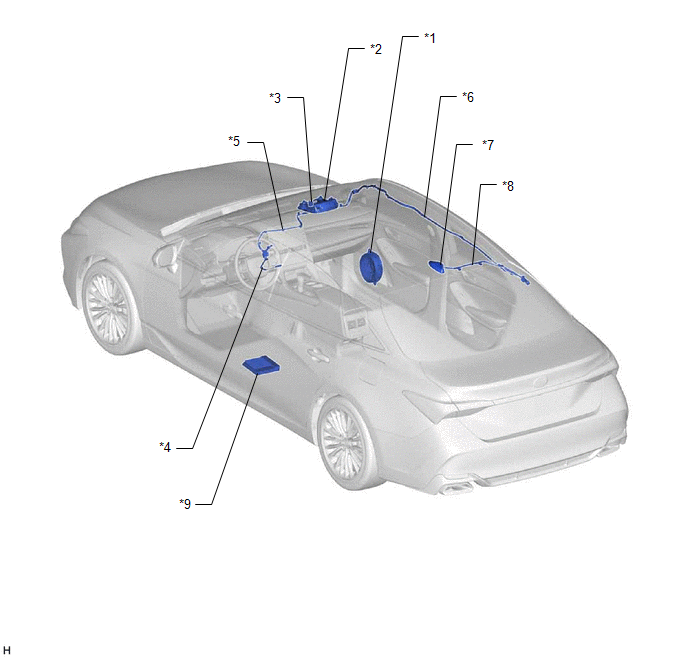
|
*1 | FRONT NO. 1 SPEAKER ASSEMBLY RH |
*2 | ROOF CONSOLE BOX SUB-ASSEMBLY
- MANUAL (SOS) SWITCH |
|
*3 | TELEPHONE MICROPHONE ASSEMBLY |
*4 | NO. 6 ANTENNA CORD SUB-ASSEMBLY |
|
*5 | NO. 4 ANTENNA CORD SUB-ASSEMBLY |
*6 | NO. 3 ANTENNA CORD SUB-ASSEMBLY |
|
*7 | TELEPHONE ANTENNA ASSEMBLY
- GPS - SDARS - Telephone Main |
*8 | NO. 2 ANTENNA CORD SUB-ASSEMBLY |
|
*9 | STEREO COMPONENT AMPLIFIER ASSEMBLY (for 14 Speakers) |
- | - |
Precaution
PRECAUTION
PRECAUTION FOR DISCONNECTING CABLE FROM NEGATIVE AUXILIARY BATTERY TERMINAL
NOTICE:
When
disconnecting the cable from the negative (-) auxiliary battery
terminal, initialize the following systems after the terminal is
reconnected.
|
System Name | See Procedure |
|
Lane Departure Alert System (w/ Steering Control) |
 |
|
Intelligent Clearance Sonar System |
|
Parking Assist Monitor System |
|
Panoramic View Monitor System |
|
Pre-collision System |
|
Lighting System (for HV Model with Cornering Light) |
PRECAUTION FOR TOYOTA ENTUNE SYSTEM
(a) If any of the following parts are replaced, refer to Initialization.
Click here
NOTICE:
If
registration is not performed after replacing any of the following
parts, the remote door lock and unlock and remote engine start and stop
will not be available.
(1) DCM (telematics transceiver)
Problem Symptoms Table
PROBLEM SYMPTOMS TABLE
NOTICE:
- When replacing the radio receiver assembly or navigation ECU, always
replace it with a new one. If a radio receiver assembly or navigation
ECU which was installed to another vehicle is used, the following may
occur:
- A communication malfunction DTC may be stored.
- The radio and display receiver assembly or navigation ECU may not operate normally.
- If the DCM (telematics transceiver) has been replaced, perform the DCM Activation procedure.
Click here 
- Before replacing the DCM (telematics transceiver), refer to Registration.
Click here
HINT:
- Use the table below to help determine the cause of problem symptoms. If
multiple suspected areas are listed, the potential causes of the
symptoms are listed in order of probability in the "Suspected Area"
column of the table. Check each symptom by checking the suspected areas
in the order they are listed. Replace parts as necessary.
- Inspect the fuses and relays related to this system before inspecting the suspected areas below.
Entune On-screen Message |
Symptom | Suspected Area |
Link |
|
A message is temporarily displayed indicating to try again after waiting for a while because the lines are busy |
This
is caused when there is a problem with the radio wave signal conditions
or when the call center is busy. This is not a malfunction. (Inform the
customer that this is not a malfunction and ask them to use the system
as is.) | - |
|
Contact the call center |
- |
| Radio and display receiver assembly |
|
|
DCM (Telematics Transceiver) |
|
|
A
message is displayed indicating to try again after waiting for a while
because information cannot be retrieved due to a busy line, etc. |
Wait for a while and perform the operation again in a different location |
- |
| Contact the call center |
- |
| Radio and display receiver assembly |
|
|
DCM (Telematics Transceiver) |
|
|
A message is displayed indicating to try again because information was not able to be retrieved |
Contact the call center |
- |
| Radio and display receiver assembly |
|
|
DCM (Telematics Transceiver) |
|
|
A message is displayed indicating to try again after waiting for a while because communication is being setup |
The system is trying to detect the DCM (telematics transceiver). Wait for a while and perform the operation again |
- |
| Contact the call center |
- |
| Radio and display receiver assembly |
|
|
DCM (Telematics Transceiver) |
|
|
A message is displayed indicating to move the vehicle into a communication service area as it is outside a service area |
Wait for a while and perform the operation again in a different location (Within the communication service area) |
- |
| Contact the call center |
- |
| Radio and display receiver assembly |
|
|
DCM (Telematics Transceiver) |
|
|
A message is displayed indicating to move the vehicle to where a GPS signal can be received because the time data is old |
Proceed to "GPS Mark is not Displayed" |
|
|
If the GPS mark is displayed, wait for a while and perform the operation again in a different location |
- |
| If the problem symptom is duplicated, replace the radio and display receiver assembly |
|
|
A message is displayed indicating that this service is not available now |
Explain to the customer that the service is currently not available. |
- |
|
A
message is displayed indicating to ask the dealer about applying for
the service as it is necessary to create a contract before using the
service | Check the status of the paid service contract. |
- |
| Contact the call center |
- |
Destination Function |
Symptom | Suspected Area |
Link |
|
Cannot contact call center when Call Dest. Assist is selected on Destination Assist Connect screen |
Contact Telematics Service Provider to inquire about network status |
- |
| Proceed to "UNABLE TO CONNECT TO CALL CENTER" |
|
|
Proceed to "DCM Data Signal Circuit between Navigation ECU and DCM" |
|
|
Radio and display receiver assembly |
|
|
DCM (Telematics Transceiver) |
|
|
Other caller's voice volume cannot be adjusted using the Destination Assist Connect screen |
Radio and display receiver assembly |
|
Dynamic Voice Recognition |
Symptom | Suspected Area |
Link |
|
Does not recognize voice commands performed to contact support center |
Check if the Toyota Entune System service is available |
- |
| Check if the normal voice recognition function is operating correctly |
|
|
Proceed to "Does not Recognize Voice Commands Performed to Contact Support Center" |
|
|
The microphone button on the keyboard input screen does not become enabled |
Check if the Toyota Entune System service is available |
- |
| Proceed to "UNABLE TO CONNECT TO CALL CENTER" |
|
Toyota Entune App Suite Connect Function |
Symptom | Suspected Area |
Link |
|
Toyota Entune App Suite Connect function error message is displayed on the screen |
Follow on screen instructions |
- |
| Proceed to "Confirm Cellular Phone Functionality" |
|
|
Proceed to "Confirm Vehicle Headunit Functionality" |
|
|
Proceed to "App Suite Connect Reset Procedure" in Operation Check |
|
|
Radio and display receiver assembly |
|
|
Toyota Entune App Suite Connect and services are not operating as expected |
Proceed to "Confirm Cellular Phone Functionality" |
|
|
Proceed to "Confirm Vehicle Headunit Functionality" |
|
|
Proceed to "App Suite Connect Reset Procedure" in Operation Check |
|
|
Radio and display receiver assembly |
|
|
Toyota
Entune App Suite Connect voice recognition is not possible (Voice
recognition on the audio and visual system*1 or navigation system*2 is
normal) | Proceed to "Confirm Cellular Phone Functionality" |
|
|
Proceed to "Confirm Vehicle Headunit Functionality" |
|
|
Proceed to "App Suite Connect Reset Procedure" in Operation Check |
|
|
Radio and display receiver assembly |
|
|
Sound quality of Toyota Entune App Suite Connect function is poor |
Check that cellular phone handset volume is turned up |
- |
| Check that adequate signal is maintained while the vehicle is being driven |
- |
| Proceed to "Confirm Cellular Phone Functionality" |
|
|
Proceed to "Confirm Vehicle Headunit Functionality" |
|
|
Proceed to "App Suite Connect Reset Procedure" in Operation Check |
|
|
Radio and display receiver assembly |
|
- *1: w/o Navigation System
- *2: w/ Navigation System
System Description
SYSTEM DESCRIPTION
DESCRIPTION
- Toyota Entune allows the vehicle to receive information from the call
center and links the information to the audio and visual system*1 or
navigation system*2. Toyota Entune permits the driver to use the
received information, such as destination information, on the audio and
visual system*1 or navigation system*2.
- Toyota Entune provides the following services: Destination Assist
Connect, Dynamic Navigation, Dynamic Voice Recognition, App Suite
Connect, Safety Connect, Remote Connect.
- For details about Safety Connect, refer to Safety Connect System.
Click here 
- For details about Remote Connect, refer to Telematics System.
Click here
- For details about Service Connect, go to http://www.toyota.com/Entune/.
- Toyota Entune consists mainly of a telephone microphone assembly, DCM
(telematics transceiver), radio and display receiver assembly, and
telephone antenna assembly.
- *1: w/o Navigation System
- *2: w/ Navigation System
FUNCTION OF MAIN COMPONENTS
|
Component | Outline |
|
Telephone Microphone Assembly | Receives user's voice. |
|
DCM (Telematics Transceiver) |
- Sends and receives content information.
- Connects to the call center when the Destination Assist Connect service etc. is active.
|
| Radio and Display Receiver Assembly |
Sends and receives the microphone voice signal. |
|
Telephone Antenna Assembly | GPS Antenna |
Receives signals from GPS satellites and sends these signals to the DCM (telematics transceiver). |
|
SDARS (Satellite Radio) Antenna | Receives radio signals from SXM satellites. |
|
Telephone Antenna (Main) |
- This antenna is for cellular phones. It supports transmission and reception of signals in frequency bands for cellular phones.
- Sends signals from the DCM (telematics transceiver) and receives signals from the call center or other phones.
|
| Navigation Antenna Assembly |
Telephone Antenna (Sub) |
- This antenna is for cellular phones. It supports transmission and reception of signals in frequency bands for cellular phones.
- Receives signals from the call center or other phones.
|
| Speakers |
Outputs the call center advisor's voice. |
|
Stereo Component Amplifier Assembly (for 14 Speakers) |
Sends the call center adviser's voice to the speakers. |
SERVICES FUNCTION
(a) Toyota Entune App Suite Connect
- Toyota Entune App Suite Connect enables the usable content of a cellular
phone to be displayed on and operated from the radio and display
assembly screen.
- Toyota Entune App Suite Connect is divided into two categories, infotainment and fleet*1.
- As "Bluetooth" communication is used for the communication between a
cellular phone and the radio and display receiver assembly, before using
the Toyota Entune App Suite Connect function on the audio and visual
system*2 or navigation system*3, the cellular phone needs to be
registered to the audio and visual system*2 or navigation system*3 as a
"Bluetooth" device. For details regarding Toyota Entune App Suite
Connect operations, each of the applications and compatible phones,
refer to http://www.toyota.com/Entune/.
- *1: Fleet is only available on vehicles with a DCM (telematics transceiver).
- *2: w/o Navigation System
- *3: w/ Navigation System
(b) Destination Assist Connect (w/ Navigation System)
- Downloads the user's desired destination information to the navigation function after the call center is told the destination.
- Stores the information downloaded in the navigation function so the information can be reused as required.
- Destination Assist Connect is an in-vehicle service that allows
subscribers to request directions to any location. Subscribers are
connected to an agent through the Destination Assist button and may ask
the agent to download the location of any destination to the navigation
function in the vehicle. Agents are able to locate specific Points Of
Interest (POI's) by search terms, locate specific addresses, or provide
Zagat-rated restaurants as premium POI's. Agents are able to search for
POI's using the distance from the vehicle, from a city, or from another
POI. The navigation function can store up to 5 POI's at a time, which
can be added to the device queue as the first or last entry, or as a
replacement for all entries.
(c) Dynamic Navigation (w/ Navigation System)
- Dynamic navigation searches the server for the latest map data and
traffic information, etc., and depending on the latest traffic status
and other data, optimizes the route and updates the map.
- Dynamic navigation requires a contract, and a full update of the map
database in the navigation ECU should be performed every 3 years.
(d) Dynamic Voice Recognition
By
performing the voice recognition process with the server, natural talk
input and other interactive voice operations besides the specified
commands can be performed. In addition, by storing all of the user's
utterances, the server will learn, and be able to perform voice
recognition with greater accuracy.
System Diagram
SYSTEM DIAGRAM
w/o Navigation System
 w/ Navigation System
Terminals Of Ecu
TERMINALS OF ECU
DCM (TELEMATICS TRANSCEIVER)
|
*a | to Telephone Antenna (Sub) |
*b | to Telephone Antenna (Main) |
|
*c | to GPS Antenna |
- | - |
|
Terminal No. (Symbol) | Wiring Color |
Terminal Description | Condition |
Specified Condition |
|
G11-1 (USB-) | GR |
USB communication line |
- | - |
|
G11-2 (USB+) | GR |
USB communication line |
- | - |
|
G11-6 (USBS) - Body ground |
Shielded - Body ground |
Shield ground | Always |
Below 1 Ω |
|
G11-3 (USBG) - Body ground |
GR - Body ground | DCM (Telematics Transceiver) power supply ground signal |
Always | Below 1 Ω |
|
G11-4 (VOT+) - G9-4 (E) |
R - BR | Sent voice signal |
Calling while using the operator service |
A waveform synchronized with the voice signals received voice is output |
|
G11-5 (USBV) - G9-4 (E) |
L - BR | DCM (Telematics Transceiver) power supply signal |
Power switch off | Below 1 V |
|
Power switch on (IG) |
4.5 to 5.25 V |
|
G11-7 (VOT-) - G9-4 (E) |
G - BR | Sent voice signal |
Calling while using the operator service |
A waveform synchronized with the received voice is output |
|
G11-8 (VOR-) - G9-4 (E) |
W - BR | Receive voice signal |
Receiving a call while using the operator service |
A waveform synchronized with the sent voice is output |
|
G11-9 (VOR+) - G9-4 (E) |
B - BR | Receive voice signal |
Receiving a call while using the operator service |
A waveform synchronized with the sent voice is output |
RADIO AND DISPLAY RECEIVER ASSEMBLY
|
Terminal No. (Symbol) | Wiring Color |
Terminal Description | Condition |
Specified Condition |
|
G108-2 (USB-)* | BR |
USB communication line |
- | - |
|
G108-1 (USB+)* | V |
USB communication line |
- | - |
|
G108-3 (USBS) - Body ground* |
Shielded - Body ground |
Shield ground | Always |
Below 1 V |
|
G1-15 (VOT+) - G3-1 (GND1) |
B - BR | Sent voice signal |
Destination assist service in use and vehicle occupant speaking to operator |
A waveform synchronized with the sent voice is output |
|
G1-10 (USBV) - G3-1 (GND1) |
L - BR | DCM (Telematics transceiver) power supply |
Power switch on (ACC) |
4.75 to 5.25 V |
|
Power switch off | A waveform synchronized with sound is output |
|
G1-16 (VOT-) - G3-1 (GND1) |
W - BR | Sent voice signal |
Destination assist service in use and vehicle occupant speaking to operator |
A waveform synchronized with the sent voice is output |
|
G1-14 (VOR-) - G3-1 (GND1) |
G - BR | Receive voice signal |
Destination assist service in use and operator speaking to vehicle occupant |
A waveform synchronized with the received voice is output |
|
G1-13 (VOR+) - G3-1 (GND1) |
R - BR | Receive voice signal |
Destination assist service in use and operator speaking to vehicle occupant |
A waveform synchronized with the received voice is output |
NAVIGATION ECU (w/ Navigation System)

|
Terminal No. (Symbol) | Wiring Color |
Terminal Description | Condition |
Specified Condition |
|
G113-2 (USB-) | BR |
USB communication line |
- | - |
|
G113-1 (USB+) | V |
USB communication line |
- | - |
|
G113-3 (USBS) - Body ground |
Shielded - Body ground |
Shield ground | Always |
Below 1 V |


