Components
COMPONENTS
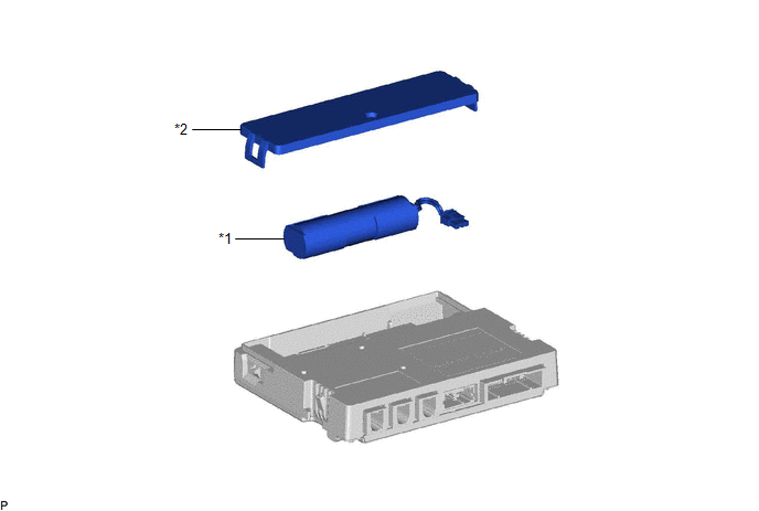
ILLUSTRATION
|
*1 | BACK-UP BATTERY |
*2 | BATTERY COVER |
Installation
INSTALLATION
PROCEDURE
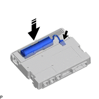
1. INSTALL BACK-UP BATTERY
(a) Install the back-up battery shown in the illustration.
 |
Install in this Direction |
NOTICE:
Make sure that the back-up battery is securely installed.
(b) Connect the connector.
NOTICE:
Make sure that the connector is connected securely.
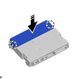
(c) Engage the 2 claws to install the battery cover as shown in the illustration.
|
|
Install in this Direction |
NOTICE:
Make sure that the battery cover is securely installed.
2. INSTALL DCM (TELEMATICS TRANSCEIVER)
Click here 
3. PERFORM INITIALIZATION
for Gasoline Model: Click here
for HV Model: Click here
Removal
REMOVAL
CAUTION / NOTICE / HINT
The necessary procedures (adjustment, calibration, initialization, or registration) that must be performed after parts are removed and installed, or replaced during back-up battery removal/installation are shown below.
Necessary Procedure After Parts Removed/Installed/Replaced (for Gasoline Model)|
Replaced Part or Performed Procedure |
Necessary Procedure | Effect/Inoperative Function When Necessary Procedures are not Performed |
Link |
|---|---|---|---|
| back-up battery |
Perform the reset back-up battery condition |
Safety Connect System |
|
|
Replaced Part or Performed Procedure |
Necessary Procedure | Effect/Inoperative Function When Necessary Procedures are not Performed |
Link |
|---|---|---|---|
| back-up battery |
Perform the reset back-up battery condition |
Safety Connect System |
|
PROCEDURE
1. REMOVE DCM (TELEMATICS TRANSCEIVER)
Click here

2. REMOVE BACK-UP BATTERY
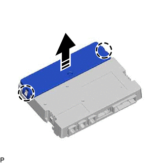
(a) Disengage the 2 claws and remove the battery cover as shown in the illustration.
 |
Remove in this Direction |
(b) Disconnect the connector and remove the back-up battery as shown in the illustration.
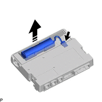
|
|
Remove in this Direction |
Toyota Avalon (XX50) 2019-2022 Service & Repair Manual > Sfi System: Brake Override System. Check For Intermittent Problems. Check Mode Procedure
Brake Override System DESCRIPTION When the vehicle is being driven, depressing the accelerator pedal sensor assembly and brake pedal will activate the brake override system to restrict driving torque. The conditions for activating the brake override system as well as the items that are controlled ar ...


