Radio Receiver Power Source Circuit
DESCRIPTION
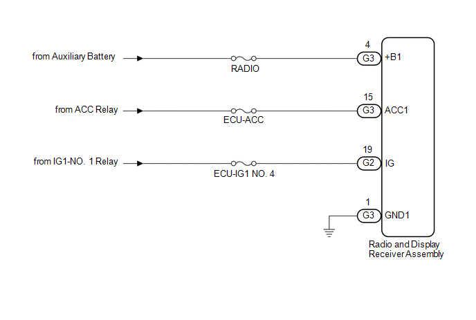
This is the power source circuit to operate the radio and display receiver assembly.
WIRING DIAGRAM
CAUTION / NOTICE / HINT
NOTICE:
Inspect the fuses for circuits related to this system before performing the following procedure.
PROCEDURE
| 1. |
CHECK HARNESS AND CONNECTOR (RADIO AND DISPLAY RECEIVER ASSEMBLY POWER SOURCE) |
(a) Disconnect the G3 and G2 radio and display receiver assembly connectors.
(b) Measure the resistance according to the value(s) in the table below.
Standard Resistance:
|
Tester Connection | Condition |
Specified Condition |
|
G3-1 (GND1) - Body ground |
Always | Below 1 Ω |
(c) Measure the voltage according to the value(s) in the table below.
Standard Voltage:
|
Tester Connection | Condition |
Specified Condition |
|
G3-4 (+B1) - G3-1 (GND1) |
Power switch off | 11 to 14 V |
|
G3-15 (ACC1) - G3-1 (GND1) |
Power switch on (ACC) |
11 to 14 V |
|
G2-19 (IG) - G3-1 (GND1) |
Power switch on (IG) |
11 to 14 V |
| OK |
 | PROCEED TO NEXT SUSPECTED AREA SHOWN IN PROBLEM SYMPTOMS TABLE |
| NG |
| REPAIR OR REPLACE HARNESS OR CONNECTOR |
Registered Device cannot be Deleted
PROCEDURE
(a) Check if a registered portable player can be deleted normally.
OK:
Registered portable player can be deleted normally.
| OK |
 | END |
| NG |
| PROCEED TO NEXT SUSPECTED AREA SHOWN IN PROBLEM SYMPTOMS TABLE |
Reverse Signal Circuit
DESCRIPTION
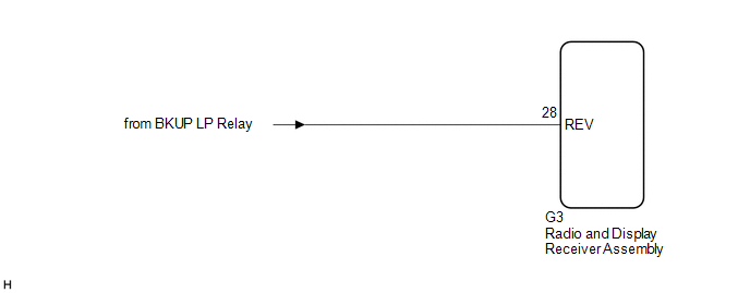
The radio and display receiver assembly receives a reverse signal from the BKUP LP relay.
WIRING DIAGRAM
PROCEDURE
(a) Move the shift lever to R and check if the back-up lights come on.
OK:
The back-up lights come on.
| NG |
 | GO TO LIGHTING SYSTEM |
|
OK |
 | |
| 2. |
CHECK HARNESS AND CONNECTOR (REVERSE SIGNAL) |
(a) Disconnect the G3 radio and display receiver assembly connector.
(b) Measure the voltage according to the value(s) in the table below.
Standard Voltage:
|
Tester Connection | Condition |
Specified Condition |
|
G3-28 (REV) - Body ground |
Power switch on (IG) Shift lever in R |
11 to 14 V |
|
G3-28 (REV) - Body ground |
Power switch on (IG) Shift lever not in R |
Below 1 V |
| OK |
| PROCEED TO NEXT SUSPECTED AREA SHOWN IN PROBLEM SYMPTOMS TABLE |
| NG |
| REPAIR OR REPLACE HARNESS OR CONNECTOR |


