How To Proceed With Troubleshooting
CAUTION / NOTICE / HINT
HINT:
- Use the following procedure to troubleshoot the audio and visual system.
- *: Use the Techstream.
PROCEDURE
|
1. | VEHICLE BROUGHT TO WORKSHOP |
|
NEXT |
 | |
| 2. |
CUSTOMER PROBLEM ANALYSIS |
- When troubleshooting, check that the problem symptoms have been
accurately identified. Preconceptions should be discarded in order to
make an accurate judgment. To clearly understand what the problem
symptoms are, it is extremely important to ask the customer about the
problem and the conditions at the time the malfunction occurred.
- Gather as much information as possible for reference. Past problems that seem unrelated may also help in some cases.
- The following 5 items are important points for problem analysis:
|
What |
Vehicle model, system name |
|
When |
Date, time, occurrence frequency |
|
Where |
Road conditions |
|
Under what conditions? |
Driving conditions, weather conditions |
|
How did it happen? |
Problem symptoms |
|
NEXT | |
| |
| 3. |
INSPECT AUXILIARY BATTERY |
(a) Measure the auxiliary battery voltage with the power switch off.
Standard Voltage:
11 to 14 V
HINT:
If the voltage is below 11 V, recharge or replace the auxiliary battery before proceeding to the next step.
|
NEXT | |
| |
(a)
Check that condensation is not likely to occur in the cabin and that
the temperature is not high or extremely low in the cabin.
OK:
Condensation is not likely being produced and the temperature is not high or extremely low.
HINT:
- A humid cabin and a rapid change in temperature may lead to condensation. Condensation in the cabin may cause a short circuit.
- The audio and visual system may not operate normally when the temperature is -20°C (-4°F) or lower, or 65°C (149°F) or higher.
| NG |
 | SET CABIN TO APPROPRIATE TEMPERATURE |
|
OK | |
| |
| 5. |
CHECK CAN COMMUNICATION SYSTEM* |
(a) Check if CAN communication system DTCs are output.
Click here 
|
Result | Proceed to |
|
CAN DTCs are not output. |
A |
| CAN DTCs are output. |
B |
| B |
| GO TO CAN COMMUNICATION SYSTEM |
|
A | |
| |
(a) Check for DTCs.
Body Electrical > Navigation System > Trouble Codes
|
Result | Proceed to |
|
DTCs are output. | A |
|
DTCs are not output. |
B |
| B |
| GO TO STEP 10 |
|
A | |
| |
(a) Clear the DTCs.
Body Electrical > Navigation System > Clear DTCs
HINT:
The present DTCs may not indicate actual malfunctions depending on the vehicle operating conditions.
|
NEXT | |
| |
(a) Recheck for DTCs.
Body Electrical > Navigation System > Trouble Codes
|
Result | Proceed to |
|
DTCs are output. | A |
|
DTCs are not output. |
B |
HINT:
- Even if the problem symptom is not confirmed, check for DTCs. This is because the system stores history DTCs.
- If more information is needed, perform a recheck using the "System Check
Mode" screen after rechecking for DTCs using the Techstream.
- Check for DTCs and inspect the area that the code indicates.
| B |
| GO TO STEP 10 |
|
A | |
| |
| 9. |
DIAGNOSTIC TROUBLE CODE CHART |
(a) Find the output DTC in Diagnostic Trouble Code Chart.
Click here
| NEXT |
| GO TO STEP 12 |
| 10. |
PROBLEM SYMPTOMS TABLE |
(a) Refer to Problem Symptoms Table.
Click here
|
Result | Proceed to |
|
Fault is not listed in Problem Symptoms Table. |
A |
| Fault is listed in Problem Symptoms Table. |
B |
HINT:
If the symptoms do not recur and no DTCs are output, attempt to reproduce the symptoms.
Click here
| B |
| GO TO STEP 12 |
|
A | |
| |
| 11. |
PERFORM TROUBLESHOOTING BASED ON PROBLEM SYMPTOM |
(a) Refer to Terminals of ECU.
Click here
|
NEXT | |
| |
(a) Adjust, repair or replace as necessary.
|
NEXT | |
| |
(a) After clearing DTCs, recheck for DTCs.
Body Electrical > Navigation System > Clear DTCs Body Electrical > Navigation System > Trouble Codes
|
NEXT | |
| |
| 14. |
PERFORM CONFIRMATION TEST |
| NEXT |
| END |
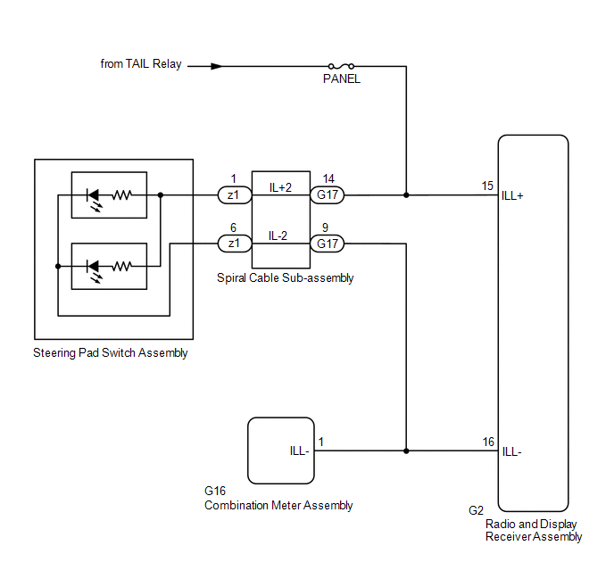
Illumination Circuit
DESCRIPTION
Power is
supplied to the radio and display receiver assembly and steering pad
switch assembly illumination when the light control switch is in the
tail or head position.
WIRING DIAGRAM
CAUTION / NOTICE / HINT
NOTICE:
- The vehicle is equipped with a Supplemental Restraint System (SRS) which
includes components such as airbags. Before servicing (including
removal or installation of parts), be sure to read the precaution for
Supplemental Restraint System.
Click here 
- Inspect the fuses for circuits related to this system before performing the following procedure.
PROCEDURE
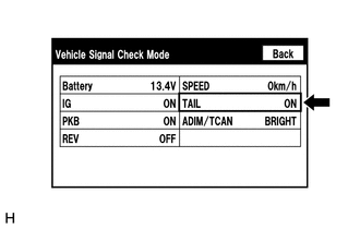
(a)
Check if the illumination for the radio and display receiver assembly,
steering pad switch assembly, heater control switch or others (hazard
switch, transmission control switch, etc.) comes on when the light
control switch is turned to the head or tail position.
|
Result | Proceed to |
|
Illumination comes on for all components except steering pad switch assembly. |
A |
| Illumination comes on for all components except radio and display receiver assembly. |
B |
| No illumination comes on (radio and display receiver assembly, hazard switch, heater control switch, etc.). |
C |
| B |
 | GO TO STEP 5 |
| C |
| GO TO LIGHTING SYSTEM |
|
A |
 | |
| 2. |
CHECK HARNESS AND CONNECTOR (ILLUMINATION SIGNAL) |
(a) Disconnect the G17 spiral cable sub-assembly connector.
(b) Measure the voltage according to the value(s) in the table below.
Standard Voltage:
|
Tester Connection | Condition |
Specified Condition |
|
G17-14 (IL+2) - Body ground |
Light control switch in tail or head position |
11 to 14 V |
| NG |
| REPAIR OR REPLACE HARNESS OR CONNECTOR |
|
OK | |
| |
| 3. |
INSPECT STEERING PAD SWITCH ASSEMBLY |
(a) Remove the steering pad switch assembly.
Click here
(b) Inspect the steering pad switch assembly.
Click here
| NG |
| REPLACE STEERING PAD SWITCH ASSEMBLY |
|
OK | |
| |
| 4. |
INSPECT SPIRAL CABLE SUB-ASSEMBLY |
(a) Remove the spiral cable sub-assembly.
Click here
(b) Inspect the spiral cable sub-assembly.
Click here
| OK |
| REPAIR
OR REPLACE HARNESS OR CONNECTOR (SPIRAL CABLE SUB-ASSEMBLY - RADIO AND
DISPLAY RECEIVER ASSEMBLY, COMBINATION METER ASSEMBLY) |
| NG |
| REPLACE SPIRAL CABLE SUB-ASSEMBLY |
| 5. |
CHECK HARNESS AND CONNECTOR (ILLUMINATION SIGNAL) |
(a) Disconnect the G2 radio and display receiver assembly connector.
(b) Measure the voltage according to the value(s) in the table below.
Standard Voltage:
|
Tester Connection | Condition |
Specified Condition |
|
G2-15 (ILL+) - Body ground |
Light control switch in tail or head position |
11 to 14 V |
| NG |
| REPAIR OR REPLACE HARNESS OR CONNECTOR |
|
OK | |
| |
| 6. |
CHECK HARNESS AND CONNECTOR (RADIO AND DISPLAY RECEIVER ASSEMBLY - COMBINATION METER ASSEMBLY) |
(a) Disconnect the G2 radio and display receiver assembly connector.
(b) Disconnect the G16 combination meter assembly connector.
(c) Measure the resistance according to the value(s) in the table below.
Standard Resistance:
|
Tester Connection | Condition |
Specified Condition |
|
G2-16 (ILL-) - G16-1 (ILL-) |
Always | Below 1 Ω |
|
G2-16 (ILL-) or G16-1 (ILL-) - Body ground |
Always | 10 kΩ or higher |
| OK |
| PROCEED TO NEXT SUSPECTED AREA SHOWN IN PROBLEM SYMPTOMS TABLE |
| NG |
| REPAIR OR REPLACE HARNESS OR CONNECTOR |