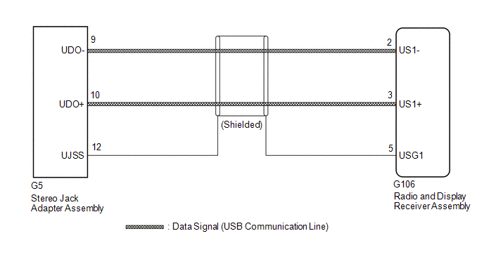
DESCRIPTION The stereo jack
adapter assembly sends the sound data signal or image data signal from a
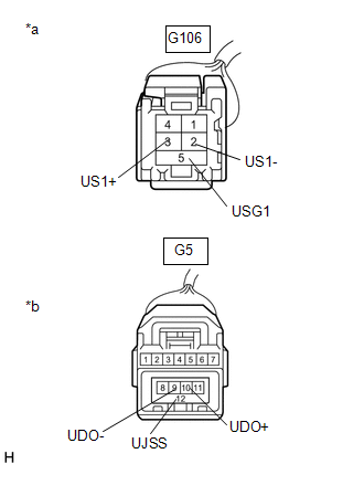
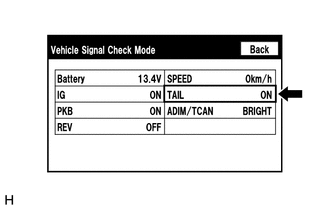
USB device to the radio and display receiver assembly via this circuit. WIRING DIAGRAM PROCEDURE 1. CHECK HARNESS AND CONNECTOR (RADIO AND DISPLAY RECEIVER ASSEMBLY - STEREO JACK ADAPTER ASSEMBLY) (a) Disconnect the G106 radio and display receiver assembly connector. (b) Disconnect the G5 stereo jack adapter assembly connector. (c) Measure the resistance according to the value(s) in the table below. Standard Resistance: Tester Connection Condition Specified Condition G106-2 (US1-) - G5-9 (UDO-) Always Below 1 Ω G106-3 (US1+) - G5-10 (UDO+) Always Below 1 Ω G106-5 (USG1) - G5-12 (UJSS) Always Below 1 Ω G106-2 (US1-) or G5-9 (UDO-) - Body ground Always 10 kΩ or higher G106-3 (US1+) or G5-10 (UDO+) - Body ground Always 10 kΩ or higher G106-5 (USG1) or G5-12 (UJSS) - Body ground Always 10 kΩ or higher *a Front view of wire harness connector (to Radio and Display Receiver Assembly) *b Front view of wire harness connector (to Stereo Jack Adapter Assembly) PROCEED TO NEXT SUSPECTED AREA SHOWN IN PROBLEM SYMPTOMS TABLE REPAIR OR REPLACE HARNESS OR CONNECTOR DIAGNOSTIC TROUBLE CODE CHART DTC No. Detection Item Link B1324 Lost Communication with Meter B1551 HD Radio Tuner Malfunction B1579 Voice Recognition Microphone Disconnected B1585 USB Device Malfunction B158D Video Signal Stoppage B158F AV Signal Stoppage (Low Battery Voltage) B15A0 LAN Master Malfunction B15A3 Stereo Component Amplifier Malfunction B15B0 Display Screen Malfunction B15B3 Radio Tuner Malfunction B15B7 Bluetooth Module Malfunction B15BA XM Tuner Malfunction B15C0 GPS Antenna Connection Malfunction(short) B15C1 GPS Antenna Connection Malfunction(break) B15C3 Speaker Output Short B15D3 Stereo Component Amplifier Disconnected B15DB Telematics Transceiver Disconnected B15F5 Air Conditioner ECU Vehicle Information Reading/Writing Processor Malfunction B15F6 Main Body ECU Vehicle Information Reading/Writing Process Malfunction B15F7 Certification ECU Vehicle Information Reading/Writing Process Malfunction B15F9 UART Communication Malfunction(for A/C) B15FE XM Tuner Antenna Disconnected B15FF XM Tuner Antenna Short C1610 Camera ECU Malfunction U0073 Sending Malfunction (Navigation to APGS) U0100 Engine ECU Communication U0129 VSC(ECB)ECU Communication U0140 Lost Communication with Body Control Module U0155 Meter ECU Communication U0164 Air Conditioner ECU Communication U0198 Lost Communication with Telematic Control Module U0265 Lost Communication with Image Processing Sensor A U0293 HV ECU Communication CAUTION / NOTICE / HINT NOTICE: Click here PROCEDURE 1. CHECK IMAGE QUALITY SETTING (a) Turn the light control switch to the tail or head position. (b) Check that the daytime screen setting on the display adjustment screen is set to on. Result Proceed to Daytime screen setting is set to on. A Daytime screen setting is set to off. B CHANGE DAYTIME SCREEN SETTING TO OFF 2. CHECK VEHICLE SIGNAL (OPERATION CHECK) (a) Enter the "Vehicle Signal Check Mode" screen. Refer to Check Vehicle Signal in Operation Check. Click here (b) Check that the display changes between ON and OFF according to the light control switch operation. OK: Light Control Switch Display Tail or head ON Off or AUTO OFF HINT: REPLACE RADIO AND DISPLAY RECEIVER ASSEMBLY PROCEED TO NEXT SUSPECTED AREA SHOWN IN PROBLEM SYMPTOMS TABLE Data Signal Circuit between Radio Receiver and Stereo Jack Adapter


OK

NG

Diagnostic Trouble Code Chart


Display does not Dim when Light Control Switch is Turned ON

A

B


OK

NG

Toyota Avalon (XX50) 2019-2022 Service & Repair Manual > Ua80e Automatic Transmission / Transaxle: Automatic Transaxle Assembly
Components COMPONENTS ILLUSTRATION *1 ENGINE ASSEMBLY WITH TRANSAXLE *2 FRONT BUMPER EXTENSION SUB-ASSEMBLY RH *3 FRONT BUMPER EXTENSION SUB-ASSEMBLY LH *4 FRONT SUSPENSION MEMBER BRACKET SUB-ASSEMBLY RH *5 FRONT SUSPENSION MEMBER BRACKET SUB-ASSEMBLY LH *6 NO. 2 ENGINE MOUNTING STAY RH Tightening t ...