DESCRIPTION
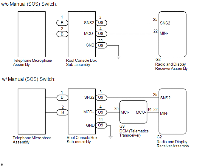
The radio and display receiver assembly, roof console box sub-assembly and telephone microphone assembly are connected to each other using the microphone connection detection signal lines.
This DTC is stored when a microphone connection detection signal line is disconnected.
|
DTC No. | Detection Item |
DTC Detection Condition | Trouble Area |
|---|---|---|---|
|
B1579 | Voice Recognition Microphone Disconnected |
Microphone signal is lost |
|
WIRING DIAGRAM
w/ Sliding Roof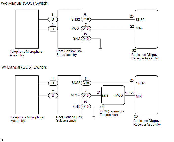 w/o Sliding Roof
CAUTION / NOTICE / HINT
NOTICE:
Click here 
Click here
PROCEDURE
|
1. | CHECK MODEL |
(a) Choose the model to be inspected.
|
Result | Proceed to |
|---|---|
|
w/ Sliding Roof | A |
|
w/o Sliding Roof | B |
| B |
 | GO TO STEP 10 |
|
| 2. |
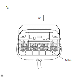
INSPECT RADIO AND DISPLAY RECEIVER ASSEMBLY |
| (a) Measure the resistance according to the value(s) in the table below. Standard Resistance:
|
|
| B |
| GO TO STEP 4 |
| C |
| REPLACE RADIO AND DISPLAY RECEIVER ASSEMBLY |
|
| 3. |
CHECK HARNESS AND CONNECTOR (RADIO AND DISPLAY RECEIVER ASSEMBLY - ROOF CONSOLE BOX SUB-ASSEMBLY) |
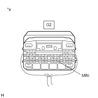
(a) Disconnect the G2 radio and display receiver assembly connector.
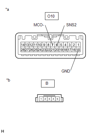
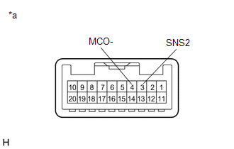
(b) Disconnect the O10 roof console box sub-assembly connector.
(c) Measure the resistance according to the value(s) in the table below.
Standard Resistance:
|
Tester Connection | Condition |
Specified Condition |
|---|---|---|
|
G2-25 (SNS2) - O10-6 (SNS2) |
Always | Below 1 Ω |
|
G2-22 (MIN-) - O10-7 (MCO-) |
Always | Below 1 Ω |
|
G2-25 (SNS2) or O10-6 (SNS2) - Body ground |
Always | 10 kΩ or higher |
|
G2-22 (MIN-) or O10-7 (MCO-) - Body ground |
Always | 10 kΩ or higher |
| OK | | GO TO STEP 8 |
| NG | | REPAIR OR REPLACE HARNESS OR CONNECTOR |
| 4. |
CHECK HARNESS AND CONNECTOR (DCM (TELEMATICS TRANSCEIVER) - ROOF CONSOLE BOX SUB-ASSEMBLY) |
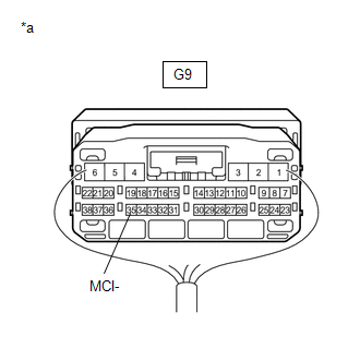
(a) Disconnect the G9 DCM (telematics transceiver) connector.
(b) Disconnect the O10 roof console box sub-assembly connector.
(c) Measure the resistance according to the value(s) in the table below.
Standard Resistance:
|
Tester Connection | Condition |
Specified Condition |
|---|---|---|
|
G9-35 (MCI-) - O10-7 (MCO-) |
Always | Below 1 Ω |
|
G9-35 (MCI-) or O10-7 (MCO-) - Body ground |
Always | 10 kΩ or higher |
| NG | | REPAIR OR REPLACE HARNESS OR CONNECTOR |
|
| 5. |
CHECK HARNESS AND CONNECTOR (RADIO AND DISPLAY RECEIVER ASSEMBLY - DCM (TELEMATICS TRANSCEIVER)) |
(a) Disconnect the G2 radio and display receiver assembly connector.
(b) Disconnect the G9 DCM (telematics transceiver) connector.
(c) Measure the resistance according to the value(s) in the table below.
Standard Resistance:
|
Tester Connection | Condition |
Specified Condition |
|---|---|---|
|
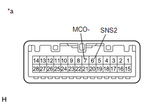
G2-22 (MIN-) - G9-19 (MCO-) |
Always | Below 1 Ω |
|
G2-22 (MIN-) or G9-19 (MCO-) - Body ground |
Always | 10 kΩ or higher |
| NG | | REPAIR OR REPLACE HARNESS OR CONNECTOR |
|
| 6. |
CHECK HARNESS AND CONNECTOR (RADIO AND DISPLAY RECEIVER ASSEMBLY - ROOF CONSOLE BOX SUB-ASSEMBLY) |
(a) Disconnect the G2 radio and display receiver assembly connector.
(b) Disconnect the O10 roof console box sub-assembly connector.
(c) Measure the resistance according to the value(s) in the table below.
Standard Resistance:
|
Tester Connection | Condition |
Specified Condition |
|---|---|---|
|
G2-25 (SNS2) - O10-6 (SNS2) |
Always | Below 1 Ω |
|
G2-25 (SNS2) or O10-6 (SNS2) - Body ground |
Always | 10 kΩ or higher |
| NG | | REPAIR OR REPLACE HARNESS OR CONNECTOR |
|
| 7. |
INSPECT DCM (TELEMATICS TRANSCEIVER) |
(a) Connect the G9 DCM (telematics transceiver) connector.
(b) Connect the G2 radio and display receiver assembly connector.
| (c) Measure the resistance according to the value(s) in the table below. Standard Resistance:
|
|
| NG | | REPLACE DCM (TELEMATICS TRANSCEIVER) |
|
| 8. |
INSPECT ROOF CONSOLE BOX SUB-ASSEMBLY |
(a) Remove the roof console box sub-assembly.
Click here
(b) Connect the B telephone microphone assembly connector.
| (c) Measure the resistance according to the value(s) in the table below. Standard Resistance:
|
|
| OK | | REPLACE RADIO AND DISPLAY RECEIVER ASSEMBLY |
|
| 9. |
INSPECT ROOF CONSOLE BOX SUB-ASSEMBLY |
(a) Remove the roof console box sub-assembly.
Click here
(b) Disconnect the B telephone microphone assembly connector.
| (c) Measure the resistance according to the value(s) in the table below. Standard Resistance:
|
|
| OK | | REPLACE TELEPHONE MICROPHONE ASSEMBLY |
| NG | | REPLACE ROOF CONSOLE BOX SUB-ASSEMBLY |
| 10. |
INSPECT RADIO AND DISPLAY RECEIVER ASSEMBLY |
| (a) Measure the resistance according to the value(s) in the table below. Standard Resistance:
|
|
| B |
| GO TO STEP 12 |
| C |
| REPLACE RADIO AND DISPLAY RECEIVER ASSEMBLY |
|
| 11. |
CHECK HARNESS AND CONNECTOR (RADIO AND DISPLAY RECEIVER ASSEMBLY - ROOF CONSOLE BOX SUB-ASSEMBLY) |
(a) Disconnect the G2 radio and display receiver assembly connector.
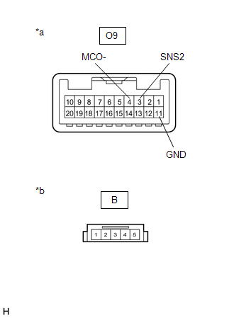
(b) Disconnect the O9 roof console box sub-assembly connector.
(c) Measure the resistance according to the value(s) in the table below.
Standard Resistance:
|
Tester Connection | Condition |
Specified Condition |
|---|---|---|
|
G2-25 (SNS2) - O9-3 (SNS2) |
Always | Below 1 Ω |
|
G2-22 (MIN-) - O9-4 (MCO-) |
Always | Below 1 Ω |
|
G2-25 (SNS2) or O9-3 (SNS2) - Body ground |
Always | 10 kΩ or higher |
|
G2-22 (MIN-) or O9-4 (MCO-) - Body ground |
Always | 10 kΩ or higher |
| OK | | GO TO STEP 16 |
| NG | | REPAIR OR REPLACE HARNESS OR CONNECTOR |
| 12. |
CHECK HARNESS AND CONNECTOR (DCM (TELEMATICS TRANSCEIVER) - ROOF CONSOLE BOX SUB-ASSEMBLY) |
(a) Disconnect the G9 DCM (telematics transceiver) connector.
(b) Disconnect the O9 roof console box sub-assembly connector.
(c) Measure the resistance according to the value(s) in the table below.
Standard Resistance:
|
Tester Connection | Condition |
Specified Condition |
|---|---|---|
|
G9-35 (MCI-) - O9-4 (MCO-) |
Always | Below 1 Ω |
|
G9-35 (MCI-) or O9-4 (MCO-) - Body ground |
Always | 10 kΩ or higher |
| NG | | REPAIR OR REPLACE HARNESS OR CONNECTOR |
|
| 13. |
CHECK HARNESS AND CONNECTOR (RADIO AND DISPLAY RECEIVER ASSEMBLY - DCM (TELEMATICS TRANSCEIVER)) |
(a) Disconnect the G2 radio and display receiver assembly connector.
(b) Disconnect the G9 DCM (telematics transceiver) connector.
(c) Measure the resistance according to the value(s) in the table below.
Standard Resistance:
|
Tester Connection | Condition |
Specified Condition |
|---|---|---|
|
G2-22 (MIN-) - G9-19 (MCO-) |
Always | Below 1 Ω |
|
G2-22 (MIN-) or G9-19 (MCO-) - Body ground |
Always | 10 kΩ or higher |
| NG | | REPAIR OR REPLACE HARNESS OR CONNECTOR |
|
| 14. |
CHECK HARNESS AND CONNECTOR (RADIO AND DISPLAY RECEIVER ASSEMBLY - ROOF CONSOLE BOX SUB-ASSEMBLY) |
(a) Disconnect the G2 radio and display receiver assembly connector.
(b) Disconnect the O9 roof console box sub-assembly connector.
(c) Measure the resistance according to the value(s) in the table below.
Standard Resistance:
|
Tester Connection | Condition |
Specified Condition |
|---|---|---|
|
G2-25 (SNS2) - O9-3 (SNS2) |
Always | Below 1 Ω |
|
G2-25 (SNS2) or O9-3 (SNS2) - Body ground |
Always | 10 kΩ or higher |
| NG | | REPAIR OR REPLACE HARNESS OR CONNECTOR |
|
| 15. |
INSPECT DCM (TELEMATICS TRANSCEIVER) |
(a) Connect the G9 DCM (telematics transceiver) connector.
(b) Connect the G2 radio and display receiver assembly connector.
| (c) Measure the resistance according to the value(s) in the table below. Standard Resistance:
|
|
| NG | | REPLACE DCM (TELEMATICS TRANSCEIVER) |
|
| 16. |
INSPECT ROOF CONSOLE BOX SUB-ASSEMBLY |
(a) Remove the roof console box sub-assembly.
Click here
(b) Connect the B telephone microphone assembly connector.
| (c) Measure the resistance according to the value(s) in the table below. Standard Resistance:
|
|
| OK | | REPLACE RADIO AND DISPLAY RECEIVER ASSEMBLY |
|
| 17. |
INSPECT ROOF CONSOLE BOX SUB-ASSEMBLY |
(a) Remove the roof console box sub-assembly.
Click here
(b) Disconnect the B telephone microphone assembly connector.
| (c) Measure the resistance according to the value(s) in the table below. Standard Resistance:
|
|
| OK | | REPLACE TELEPHONE MICROPHONE ASSEMBLY |
| NG | | REPLACE ROOF CONSOLE BOX SUB-ASSEMBLY |
Toyota Avalon (XX50) 2019-2022 Owners Manual > Opening and closing
the windows: Power windows
Opening and closing procedures The power windows can be opened and closed using the switches. Operating the switch moves the windows as follows: Closing One-touch closing* Opening One-touch opening* *: To stop the window partway, operate the switch in the opposite direction. Window lock switch Press ...